Welding electrodes and adapter therefor

a technology of resistive spot welding and electrodes, which is applied in the direction of cooling electrodes, electrode maintenance, manufacturing tools, etc., can solve the problems of complex process, electrodes to catastrophically collapse to the detriment of welding operation, and distortion commonly referred to as “mushrooming”

Active Publication Date: 2015-11-26
PRUCHER BRYAN
View PDF12 Cites 6 Cited by
  • Summary
  • Abstract
  • Description
  • Claims
  • Application Information

AI Technical Summary

Benefits of technology

[0022]In one aspect, the present invention provides means for demarking an electrode body or caps at its maximum useful life with a “maximum life line marker”. The maximum life line marker provides the welding operat

Problems solved by technology

This process is complex, involving the interaction of electrical, thermal, mechanical, metallurgical, and surface phenomena.
The recurring heat and compression cycles associated with welding result in mechanical fatigue that leads to distortion commonly referred to as “mushrooming”.
Electrodes can have their useful life extended by re-dressing the cap multiple times. They cannot, however, be dressed too close to the end of the cooling cavity as that would cause the electrode to catastrophically collapse to the detriment of the welding operation.
However, coated metals, such as galvanized and/or aluminized steel, used in automobile body manufacturing require higher current levels to produce a weld.
This dramatically increases electrode deformation, resulting in a significant reduction in usable electrode life.
Therefore, the addition of a layer of zinc or any other highly electro-negative coating material to the work-piece surfaces reduces the interface contact resistance.
These elevat

Method used


Image

  • Welding electrodes and adapter therefor
  • Welding electrodes and adapter therefor
  • Welding electrodes and adapter therefor

Examples


Embodiment Construction

[0043]Throughout the ensuing description, the terms “electrode”, “electrode body” or “electrode cap” are used interchangeably to reference the replaceable portion of a welding robot.

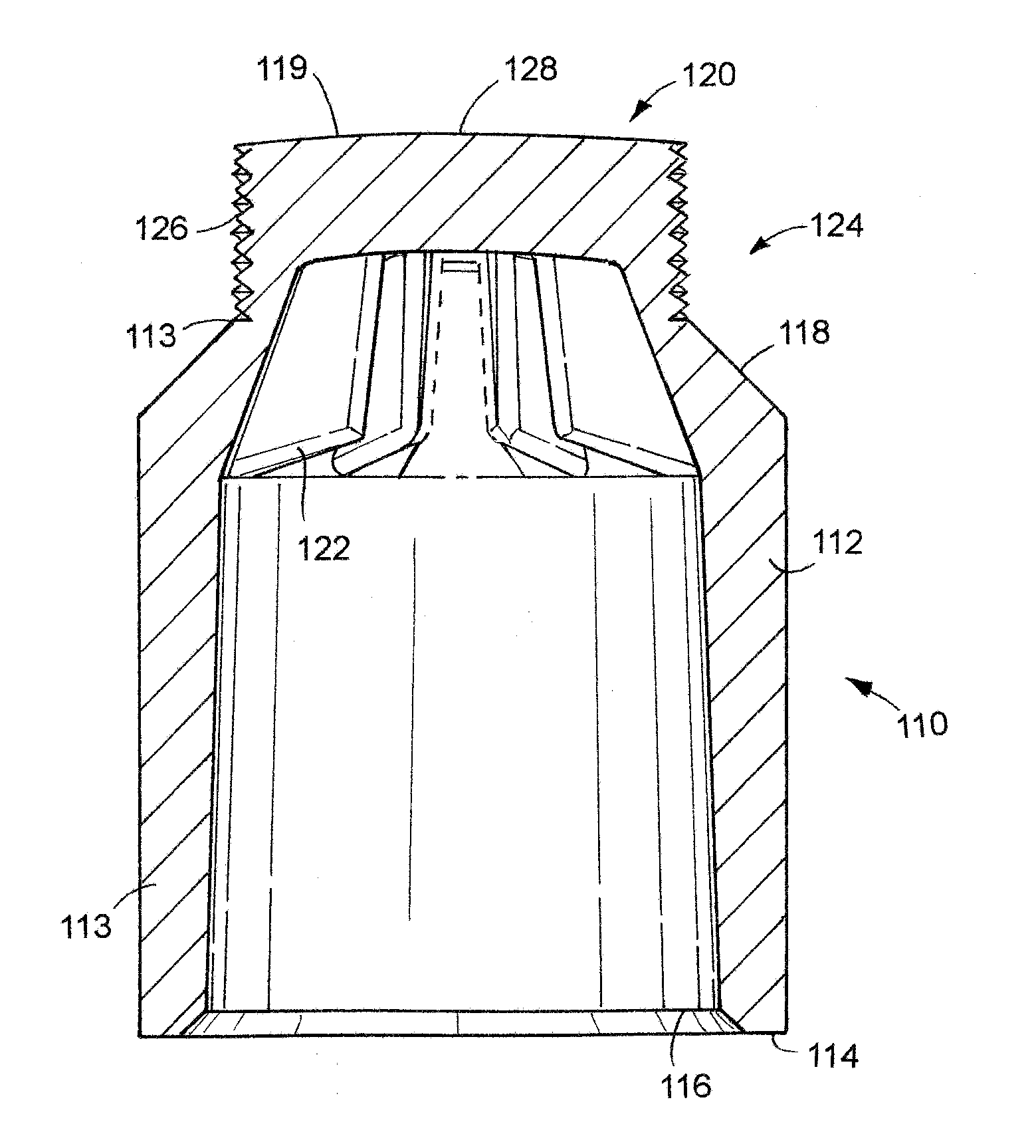
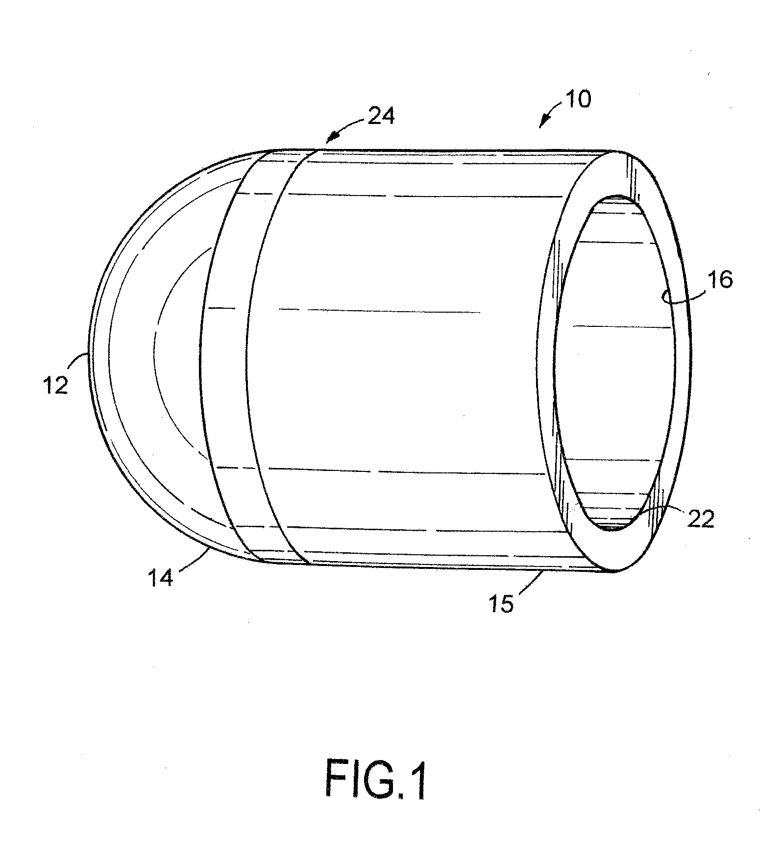
[0044]Now and with reference to the drawing, and in particular FIGS. 1 and 2, there is depicted therein an electrode body or cap 10. As shown, the body or cap 10 has an exterior planar upper surface or top 12 and an integrally formed arcuate or curvilinear circumferential shoulder 14 which merges into a cylindrical sidewall 15.

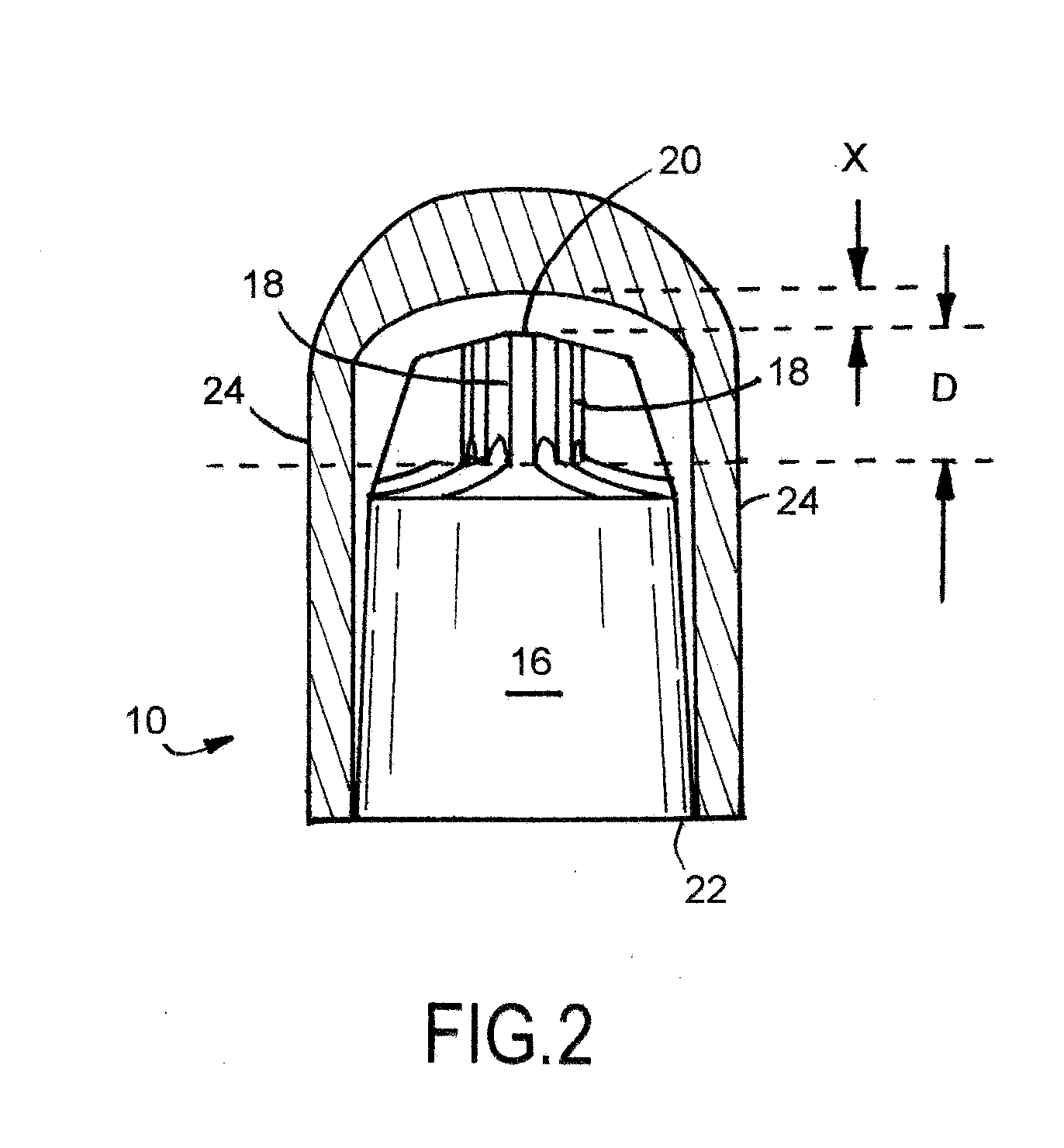
[0045]An entry 22 is provided at the end of cap opposite the top 12. The electrode or electrode body or electrode cap 10 has an internal, finned cooling cavity 16 (FIG. 2), the walls or surfaces thereof are substantially parallel to the exterior surfaces or walls and are tapered to frictionally fit onto a shank. The internal cavity 16 has a distal end point 20 which is substantially parallel to the top or spot 12 and the opposed proximal end or entrance 22.

[0046]A plurality of fins...


PUM


Abstract

An electrode cap and adapter assembly includes a cap having a useful life line inscribed thereon. The cap may be either a circumferentially configured internally finned cap or a self-dressing internally finned cap. The male/female adapter is used to mount a female cap to a male shank.

Description

CROSS-REFERENCE TO RELATED APPLICATIONS[0001]This is a completion application of Co-pending U.S. Provisional Patent Application, Ser. Nos. 62 / 002,314 and 62 / 004,562 filed May 23, 2014 and May 29, 2014 respectively, the disclosure of which is hereby incorporated by reference as well as related to previous United States Provisional Application, Serial No. 61 / 895,621, filed Oct. 25, 2013, the disclosure of which is hereby incorporated by reference as well.BACKGROUND OF THE INVENTION[0002]1. Field of Invention[0003]This invention relates, in general, to resistance spot welding equipment and, more specifically to resistance spot welding electrodes with a finned cooling cavity. More particularly, the present invention concerns replaceable welding caps or bodies for resistance spot welding electrodes. Even more particularly, the present invention concerns means and methods for determining the end point for dressing an electrode welding caps, as well as their deployment on an electrode shan...

Claims


Application Information

Patent Timeline
IPC IPC(8): B23K11/30B23K11/31
CPCB23K11/31B23K11/30B23K11/3054B23K11/3063
Inventor PRUCHER, BRYAN
Owner PRUCHER BRYAN
Why Eureka
Try Eureka