In-mold vibratile injection compression molding method and molding apparatus thereof

a technology of vibratile injection and compression molding, which is applied in the direction of optical articles, domestic applications, other domestic articles, etc., can solve the problems of reducing reducing and reducing the efficiency of molding materials. , to achieve the effect of increasing the shear rate of molding materials and improving the viscosity of molding materials

Active Publication Date: 2015-11-26
NAT TAIWAN UNIV OF SCI & TECH
View PDF4 Cites 10 Cited by
  • Summary
  • Abstract
  • Description
  • Claims
  • Application Information

AI Technical Summary

Benefits of technology

[0023]In one embodiment, the shear rate of the molding material is increased when a viscosity of the molding material in the cavity is decreased to rapidly move the molding material into the microstructure of the cavity based on the pressure sensing signal.

Problems solved by technology

The form error is obtained after molding material injected into mold cavity, which results in the optical design deviation of the plastic component due to the materials shrinkage of molding part, and the optical image quality is downgraded.
The groove filling rate is easily limited to the manufacturing process and multi-scale dimension consideration, which causes the design size and shape of the microstructure to be deviated after a molding step and debit effects on the optical property.
Besides the stress birefringence induced by the residual stress affects the optical property of the molding part, a crack, shrinkage and warped appearance and lower mechanical strength may be simultaneously induced.

Method used


Image

  • In-mold vibratile injection compression molding method and molding apparatus thereof
  • In-mold vibratile injection compression molding method and molding apparatus thereof
  • In-mold vibratile injection compression molding method and molding apparatus thereof

Examples


Embodiment Construction

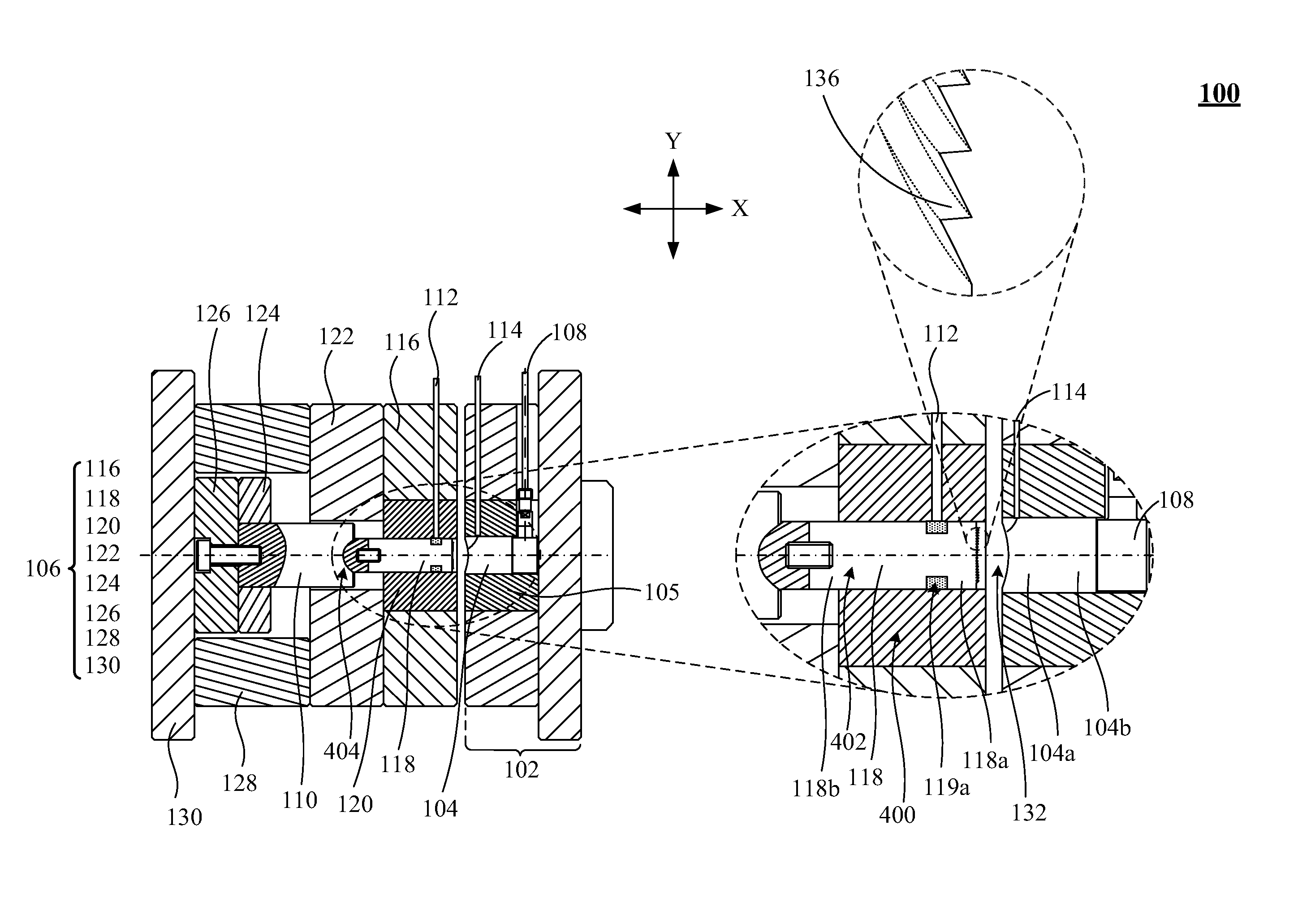
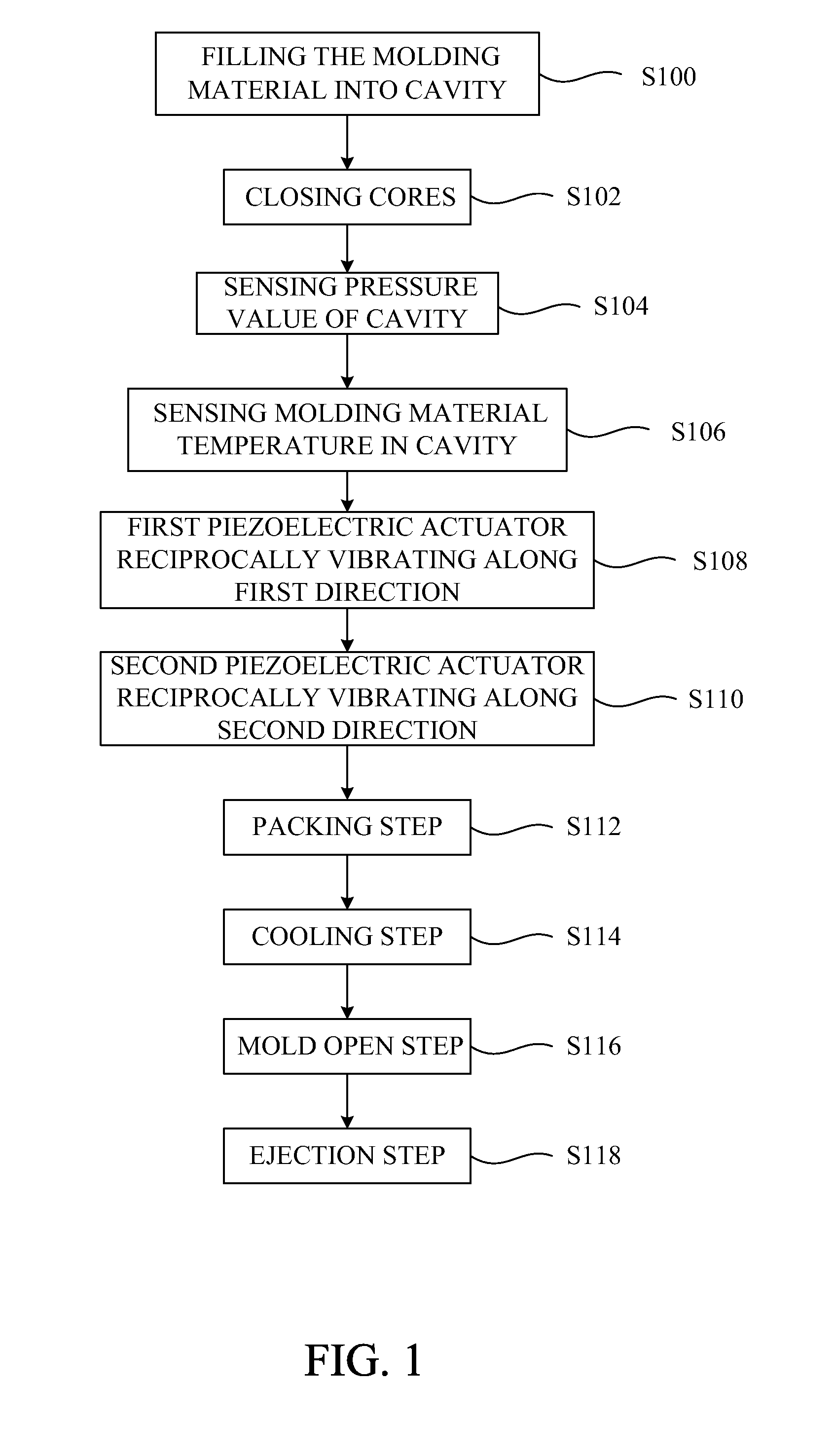
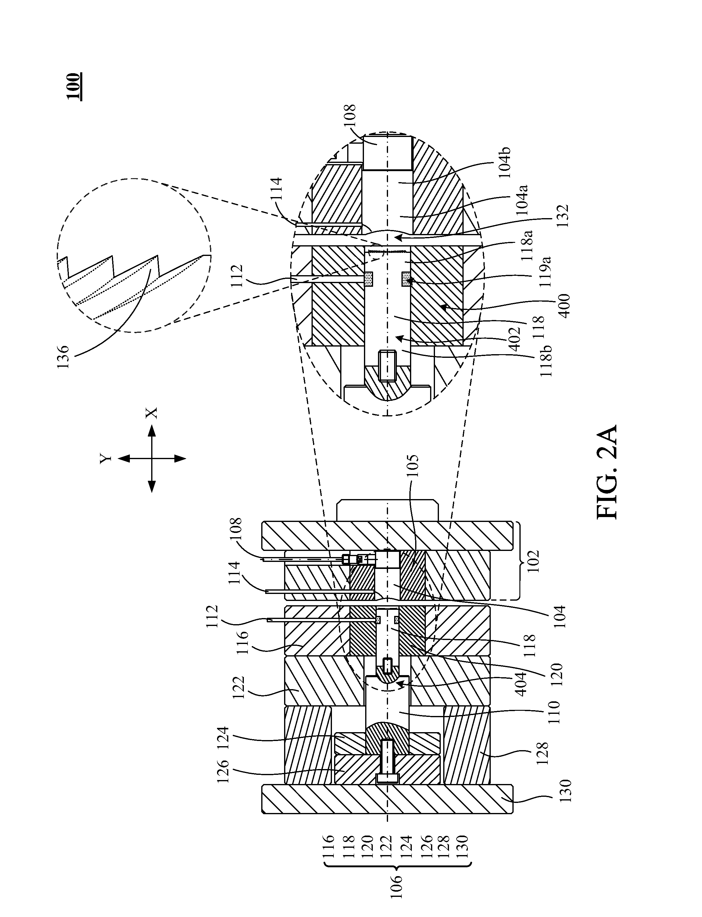
[0036]Please refer to FIG. 1 and FIGS. 2A-2F. FIG. 1 is a flow chart of performing an in-mold vibratile injection compression molding method according to one embodiment of the present invention. FIGS. 2A-2F are schematic cross-sectional process views of performing an in-mold vibratile injection compression molding method in an injection molding equipment according to one embodiment of the present invention. The in-mold vibratile injection compression molding method is performed by an in-mold vibratile injection compression molding apparatus 100, as shown in FIG. 2A. The vibratile injection molding apparatus 100 includes a stationary structure 102, a fixed core 104, a stationary retainer 105, a movable structure 106, a pressure sensor 108, a first piezoelectric actuator 110, a second piezoelectric actuator 112 and a temperature sensor 114. The movable structure 106 includes a first sustaining plate 116, a moveable core 118, a movable retainer 120, a second sustaining plate 122, a fir...


PUM

PropertyMeasurementUnit
thicknessaaaaaaaaaa
thicknessaaaaaaaaaa
temperatureaaaaaaaaaa

Abstract

An in-mold vibratile injection compression molding method and molding apparatus thereof are described. While performing a filling stage, a first piezoelectric actuator and a second piezoelectric actuator are use to vibrate the molding material along at least two directions for precisely filling the molding material into the micro-structure by adjusting the filling flow velocity of the molding material associated with the proper molding material temperature and by maintaining a molding material temperature of a skin solidified layer in the cavity between a glass transition temperature and a melting temperature in order to avoid the form error, to increase the groove filling rate and to improve the residual stress.

Description

[0001]This patent application is a continuation-in-part application and claims priority of U.S. patent application Ser. No. 13 / 492,865, entitled “IN-MOLD VIBRATILE INJECTION COMPRESSION MOLDING METHOD AND MOLDING APPARATUS THEREOF”, which is filed on Jun. 10, 2012, incorporated herein by reference.FIELD OF THE INVENTION[0002]The present invention relates to a molding method and molding apparatus thereof, and more particularly to an in-mold vibratile injection compression molding method and molding apparatus thereof.BACKGROUND OF THE INVENTION[0003]With the rapid development of the light source of light-emitted diode (LED) and solar energy, the enhancement smaller size of optoelectronic products have been provoked. Plastics materials have been widely used in precise molding optical components the optoelectronic products, especially for the mobile devices. Further, optical lens used in the optoelectronic products gradually downsizes so the hybrid optical elements (HOEs) have been deve...

Claims


Application Information

Patent Timeline
Patent Type & Authority Applications(United States)
IPC IPC(8): B29C45/56
CPCB29C45/568B29C45/561B29L2031/3406B29C2945/76381B29C2945/76257B29C2945/76006B29C45/372B29C45/76B29C2045/565B29C2945/7604B29C2945/76384B29C2945/76933B29C2945/76943B29L2011/0016
Inventor CHEN, CHAO-CHANGLEE, FENG-CHIWANG, KUN-LINYEH, CHING-HSIEN
Owner NAT TAIWAN UNIV OF SCI & TECH
Why Eureka
Try Eureka