Method of refurbishing rotogravure cylinders, rotogravure cylinders and their use

a technology of rotogravure cylinder and rotogravure, which is applied in the direction of foil printing, plate printing, coating, etc., can solve the problems of limited life time of printing process, difficult to achieve the effect of reducing the number of brittle parts, improving the stability of the process, and improving the quality of the finished produ

Active Publication Date: 2015-11-26
ICR IOANNOU SA
View PDF7 Cites 1 Cited by
  • Summary
  • Abstract
  • Description
  • Claims
  • Application Information

AI Technical Summary

Benefits of technology

[0030]Further, the present zinc layer provides excellent adhesion to the present copper support layer. In a most suitable embodiment, the provision of the copper support layer is carried out to form a brass layer at the interface of the zinc layer and the copper support layer. Thereto, the copper support layer may be deposited by means of electrodeposition or such that melting occurs at the surface of the cylinder, i.e. the interface with the zinc layer. Brass is known to have a low brittleness at ambient temperature. Also, in these use conditions, the interdiffusion of copper and zinc is not an issue.
[0031]Suitably, the present zinc layer is a zinc alloy. More preferably the present zinc layer comprises nickel, aluminium, copper and / or magnesium. One advantage of such alloy is a higher stability against interdiffusion of zinc and copper, particularly when applying the -copper- support layer by means of electroplating. The alloying elements are suitably present in low quantities, for instance less than 10 wt %, preferably less than 5 wt %, or even less than 3 wt %, or even 0.02-2 wt %. More particularly, aluminum or nickel are suitably present as primary alloying element, and magnesium and / or copper may be present in smaller quantities, for instance 0.1 to 0.8 wt % copper and less than 0.05 wt % magnesium. An upper limit to the content of the alloying element(s) results from an increase in hardness with an increase in alloying element.
[0032]It is an advantage of the present invention that the refurbishing process of rotogravure cylinder is simplified. Particularly, the step of applying an intermediate polymer layer could be eliminated in comparison with the method of
[0033]US 2011 / 0083570, thereby preventing problems with the diameter stability during a second life time of the rotogravure cylinder base.

Problems solved by technology

The disadvantage of the disclosed process is that an intermediate polymer layer is used for the construction of a refurbished rotogravure cylinder.
The disclosed intermediate polymer layer is a soft material which leads to a limited life time in printing processes due to the constantly applied forces onto the rotogravure cylinder.
Further, the process is problematic with regard to the diameter stability.
A further problem in relation to the prior art method is that the refurbishment does not result in cylinder having use-properties that are substantially the same as those of new cylinders.

Method used


Image

  • Method of refurbishing rotogravure cylinders, rotogravure cylinders and their use
  • Method of refurbishing rotogravure cylinders, rotogravure cylinders and their use

Examples


Embodiment Construction

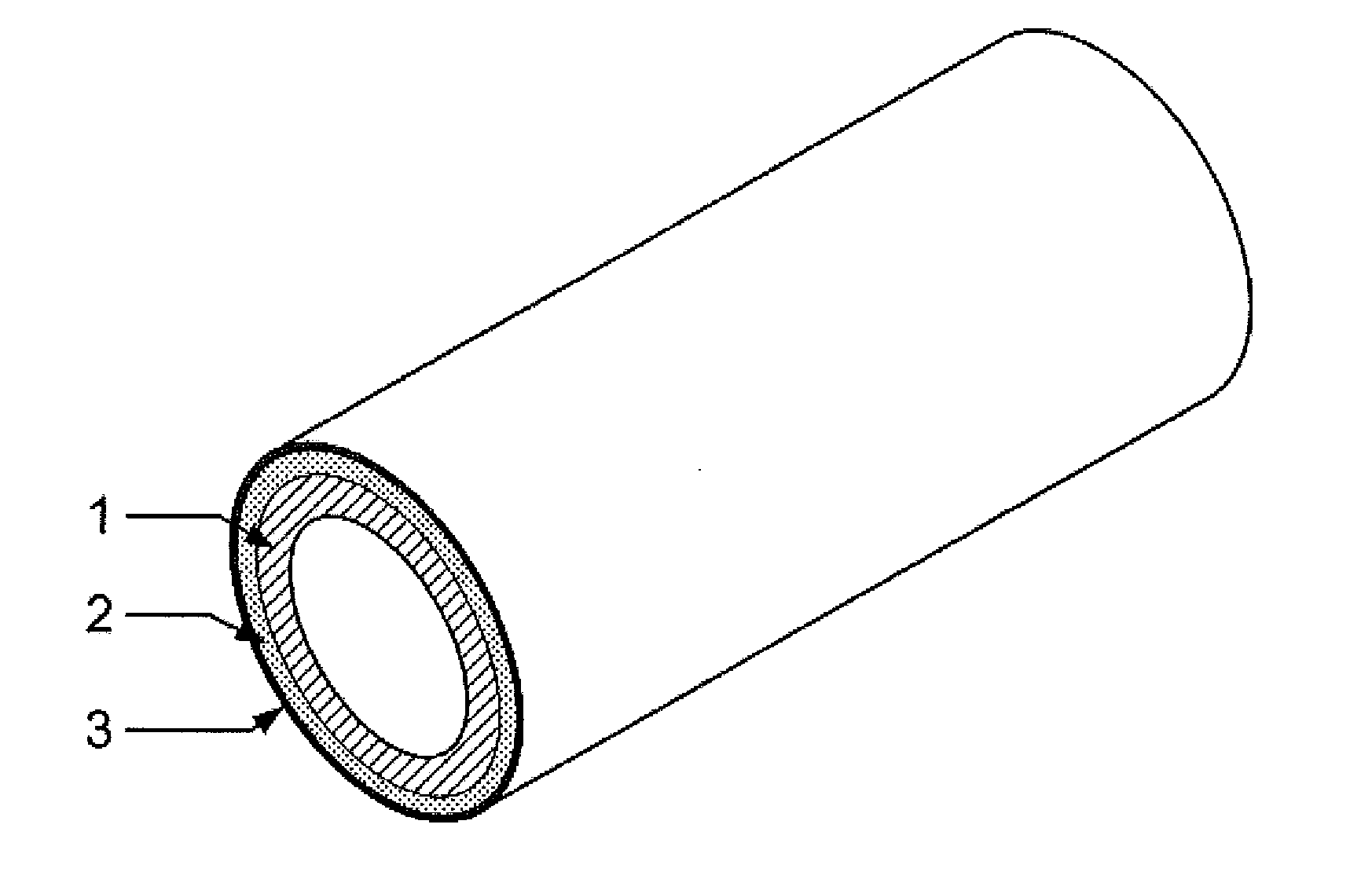
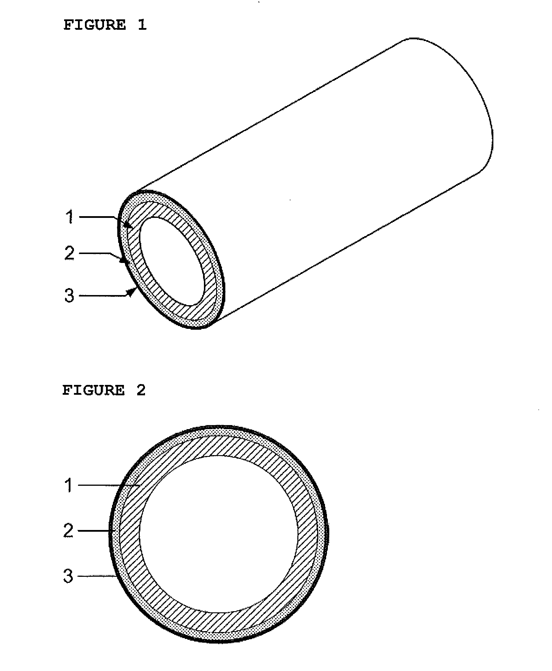
[0044]The FIGS. 1 and 2 are not drawn to scale and they are only intended for illustrative purposes. Equal reference numerals in different figures refer to identical or corresponding figures.

[0045]The term ‘rotogravure cylinders’ relates herein to rotogravure cylinders and / or any gravure cylinders used in the printing industry, particularly for the printing of packaging materials. The length of such cylinders is typically at least 1.0 meter, more preferably in the order of 1.5-2.5 meter.

[0046]The term ‘cylindrical base’ as used in the context of the present invention does not require the base to be a block-like material. Rather the base may be hollow. Alternatively, the base may comprise several layers, such as a steel core and an aluminium top layer.

[0047]The term aluminum in the present invention refers to pure aluminum, aluminum with small addition of other materials or aluminum alloys. Likewise, the term copper refers to pure copper, copper with small addition of other materials...


PUM

PropertyMeasurementUnit
diameteraaaaaaaaaa
diameteraaaaaaaaaa
diameteraaaaaaaaaa

Abstract

The rotogravure cylinder comprising a rotary gravure base and thereon a copper engraving layer is refurbished to contain a zinc layer between a gravure base and a layer package suitable for engraving and printing. This layer package for instance comprises a metallic support layer, a copper engraving layer and suitably a protection layer. Deposition of the zinc layer may be tuned for thickness variation, in combination with deposition of the layer package in a fixed thickness.

Description

FIELD OF THE INVENTION[0001]The present invention refers to a method for refurbishing rotogravure or gravure cylinders.[0002]The invention also relates to the thus obtained rotogravure cylinders.[0003]The invention further relates to the use of the rotogravure cylinders in the printing industry for the printing of packaging materials (by transfer of ink from the printing cylinder to the packaging material), such as for instance Intaglio printing processes.BACKGROUND OF THE INVENTION[0004]Rotogravure cylinders (see FIG. 1 which shows such a cylinder, and FIG. 2 which shows a typical cross section of such a cylinder) comprise of the base 1, which is usually made of steel or aluminium with a diameter as required by the printing machine, an image carrying copper layer 2 usually of 0.1 to 1 mm thick where the packaging pattern is engraved upon, and a chrome layer 3 usually 6 to 8 μm thick to increase resistance of the cylinder to wear during the printing process. In FIG. 1 the dimensions...

Claims


Application Information

Patent Timeline
Patent Type & Authority Applications(United States)
IPC IPC(8): B41N1/20B41N3/04
CPCB41N3/04B41N1/20B41F13/11B41N1/06B41N3/003
Inventor IOANNOU, IOANNIS
Owner ICR IOANNOU SA
Why Eureka
Try Eureka