Multilayer ceramic capacitor

Active Publication Date: 2015-11-26
MURATA MFG CO LTD
View PDF4 Cites 40 Cited by
  • Summary
  • Abstract
  • Description
  • Claims
  • Application Information

AI Technical Summary

Benefits of technology

[0012]According to a preferred embodiment of the present invention, a multilayer ceramic capacitor that is able to withstand deterioration of insulation resistance is provided in which the amount of Mg contained in the dielectric ceramic layers preferably is not less than 0 part by mole and not more than about 0.4 part by mole, per 100 parts by mole of Ti, and the dielectric ceramic layers of the inner layer portion preferably have a thickness of not more than about 0.55 μm, for example. This multilayer ceramic capacitor is a highly reliable multilayer ceramic capacitor in which the thickness of the dielectric ceramic layers is significantly reduced.
[0013]Further, in particular, in thin-layer regions having a thickness of not more than about 0.55 μm, the distance between ends of the internal el

Problems solved by technology

However, in a multilayer ceramic capacitor in which the dielectric ceramic layers and the internal electrodes have been reduced in thickness and increased in lamination density, if the thickness of the dielectric ceramic layers is furt

Method used


Image

  • Multilayer ceramic capacitor
  • Multilayer ceramic capacitor
  • Multilayer ceramic capacitor

Examples


Example

[0090]With respect to Reference Example 1, the amount of Mg is 1 part by mole, and the thickness of the ceramic layers defining the inner layer portion is 1.3 μm; in this case, the MTTF is 200 hours and thus, evaluated as “G”.

Example

[0091]With respect to Reference Example 2, the amount of Mg is 1 part by mole, and the thickness of the ceramic layers defining the inner layer portion is 1 μm; in this case, the MTTF is 85 hours and thus, evaluated as “G”. With respect to Reference Example 4, the amount of Mg is 1 part by mole, and the thickness of the ceramic layers defining the inner layer portion is 1 μm; in this case, the MTTF is 92 hours and thus, evaluated as “G”.

Example

[0092]Similarly, with respect to Reference Example 3, the amount of Mg is 1 part by mole, and the thickness of the ceramic layers defining the inner layer portion is 0.8 μm; in this case, the MTTF is 40 hours and thus, evaluated as “G”. With respect to Reference Example 5, the amount of Mg is 1 part by mole, and the thickness of the ceramic layers defining the inner layer portion is 0.8 μm; in this case, the MTTF is 54 hours and thus, evaluated as “G”.

[0093]Accordingly, with respect to each of Reference Examples 1 to 5, the MTTF is not less than 12 hours and thus, evaluated as “G”, while the thickness of the ceramic layers defining the inner layer portion is not less than 0.8 μm and not more than 1.3 μm. This indicates that it is difficult to reduce the thickness of the ceramic layers defining the inner layer portion.

[0094]The foregoing results therefore indicate that in thin-layer regions, if the thickness of the ceramic layers defining the inner layer portion is large, the MTTF wi...


PUM

PropertyMeasurementUnit
Grain sizeaaaaaaaaaa
Fractionaaaaaaaaaa
Fractionaaaaaaaaaa

Abstract

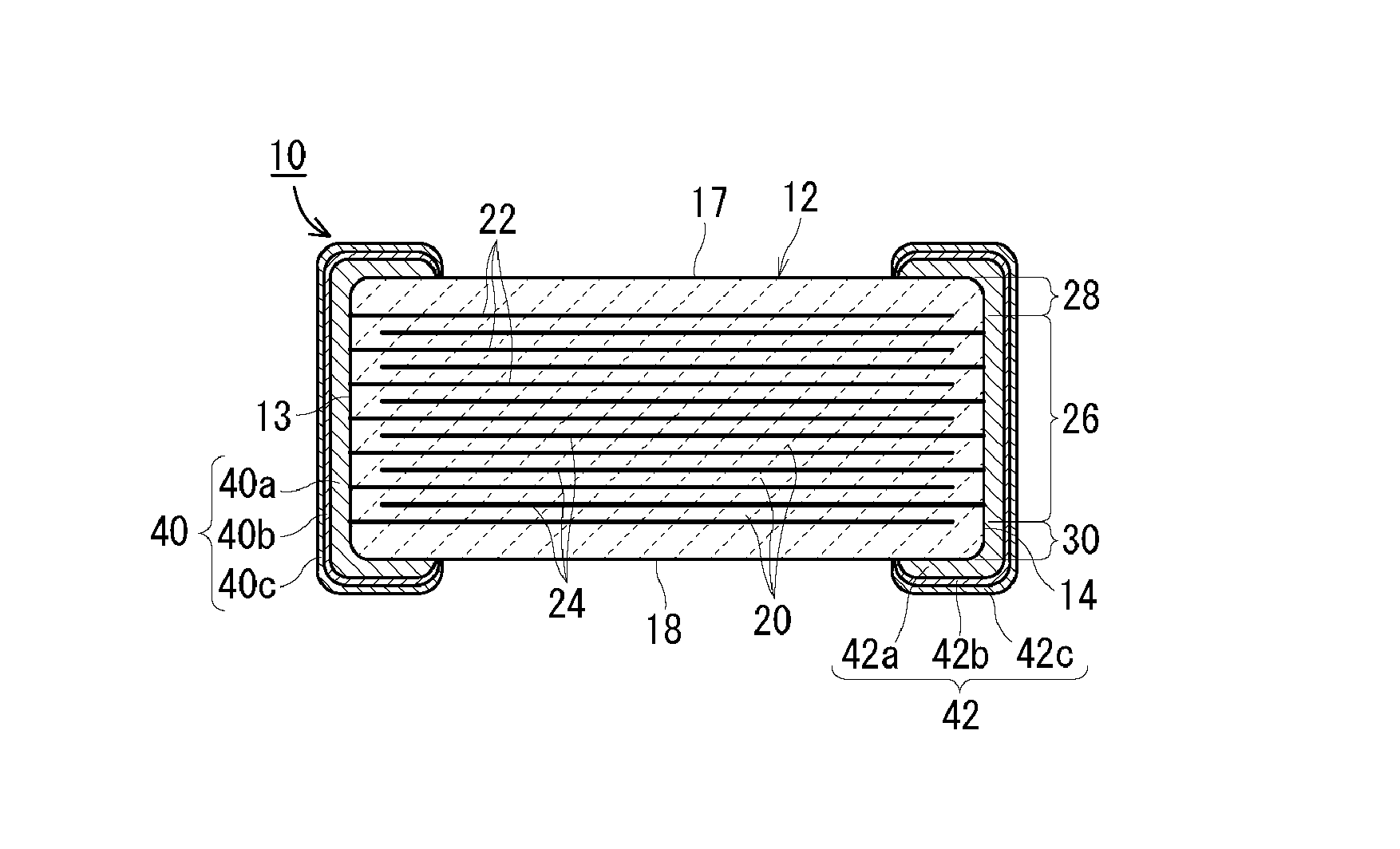
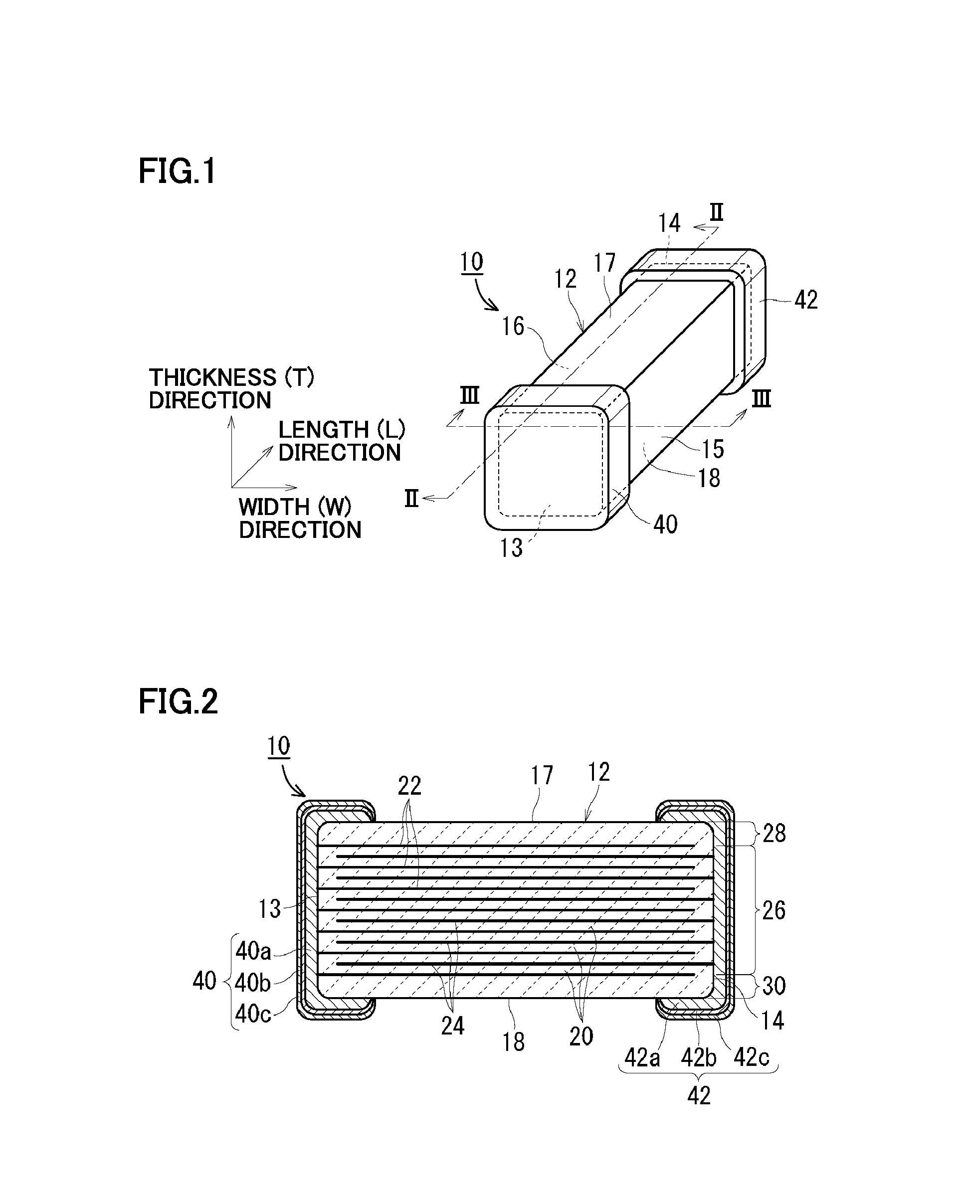
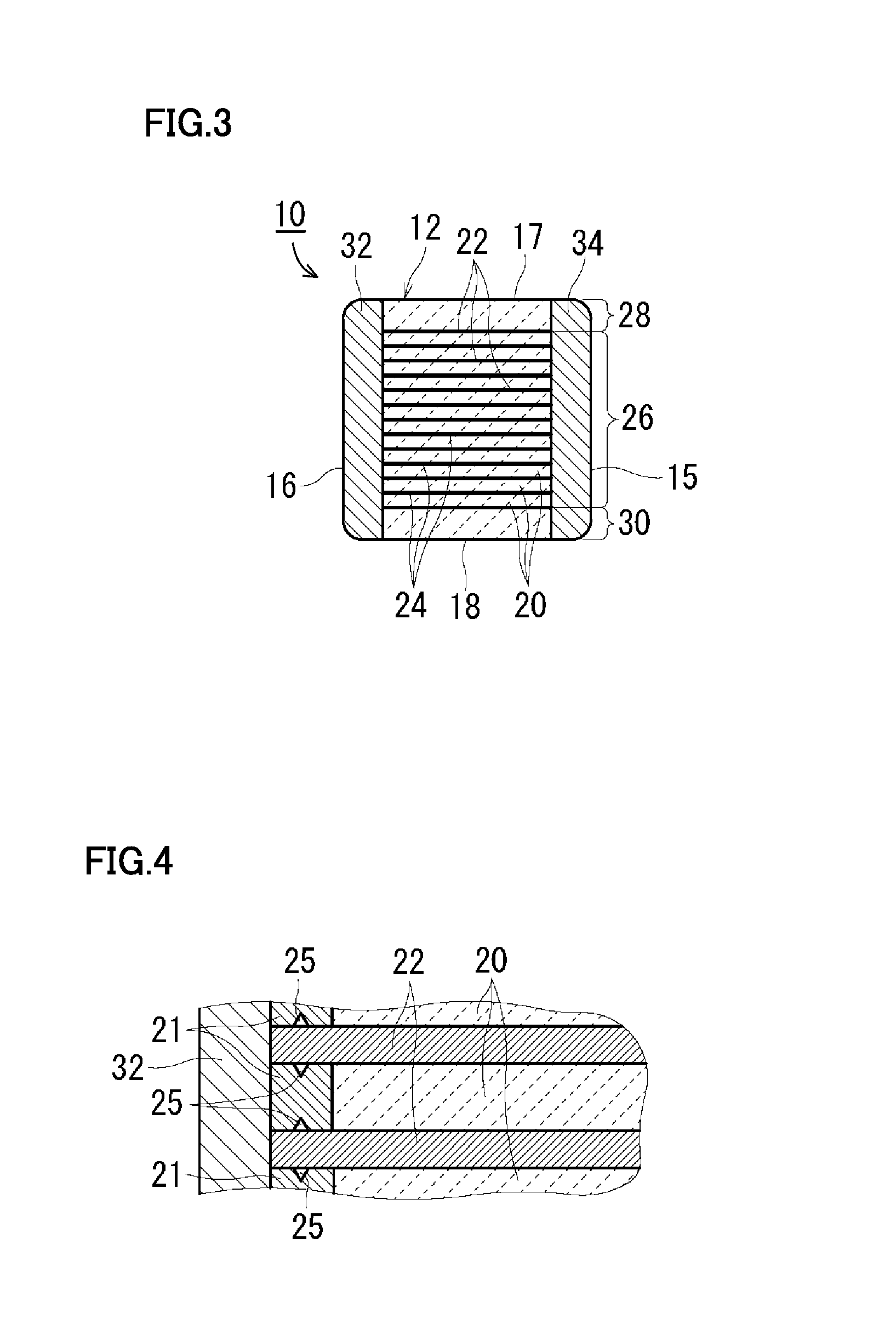
A multilayer ceramic capacitor includes a ceramic body, and external electrodes on opposite side surfaces of the ceramic body. The ceramic body includes an inner layer portion including a plurality of ceramic layers, and first and second internal electrodes each arranged at interfaces between the ceramic layers defining the inner layer portion, and also includes outer layer portions arranged on an upper surface and a lower surface of the inner layer portion. The ceramic layers defining the inner layer portion include as a main component a perovskite-type compound containing Ba and Ti. The amount of Mg contained in the ceramic layers defining the inner layer portion preferably is 0 to about 0.4 part by mole per 100 parts by mole of Ti, for example. The thickness of the ceramic layers defining the inner layer portion preferably is not more than about 0.55 μm, for example.

Description

BACKGROUND OF THE INVENTION[0001]1. Field of the Invention[0002]The present invention relates to a multilayer ceramic capacitor.[0003]2. Description of the Related Art[0004]In recent years, with the decreasing size and increasing performance of electronic components, a size reduction and an increased capacitance are required in multilayer ceramic capacitors. Such a multilayer ceramic capacitor includes, for example, a ceramic body with a rectangular parallelepiped shape, in which ceramic layers defining an inner layer portion and internal electrodes are laminated alternately, and ceramic layers defining an outer layer portion are arranged on upper and lower surfaces of the laminated body, and also includes external electrodes formed on opposite end surfaces of the ceramic body.[0005]In order to achieve a size reduction and an increased capacity in the multilayer ceramic capacitor, it is necessary to reduce the thickness and increase the lamination density of the ceramic layers defin...

Claims


Application Information

Patent Timeline
IPC IPC(8): H01G4/12H01G4/008H01G4/232H01G4/30
CPCH01G4/1227H01G4/2325H01G4/008H01G4/30H01G4/0085
Inventor MASUNARI, AKIOKANZAKI, TAISUKE
Owner MURATA MFG CO LTD
Why Eureka
Try Eureka