Aircraft and a retrofit cryogenic fuel system

a fuel system and airframe technology, applied in the field of aircraft systems, can solve the problem of low engine system efficiency

Active Publication Date: 2015-12-03
GENERAL ELECTRIC CO
View PDF4 Cites 13 Cited by
  • Summary
  • Abstract
  • Description
  • Claims
  • Application Information

AI Technical Summary

Problems solved by technology

Use of compressor air for cooling may

Method used


Image

  • Aircraft and a retrofit cryogenic fuel system
  • Aircraft and a retrofit cryogenic fuel system
  • Aircraft and a retrofit cryogenic fuel system

Examples


Embodiment Construction

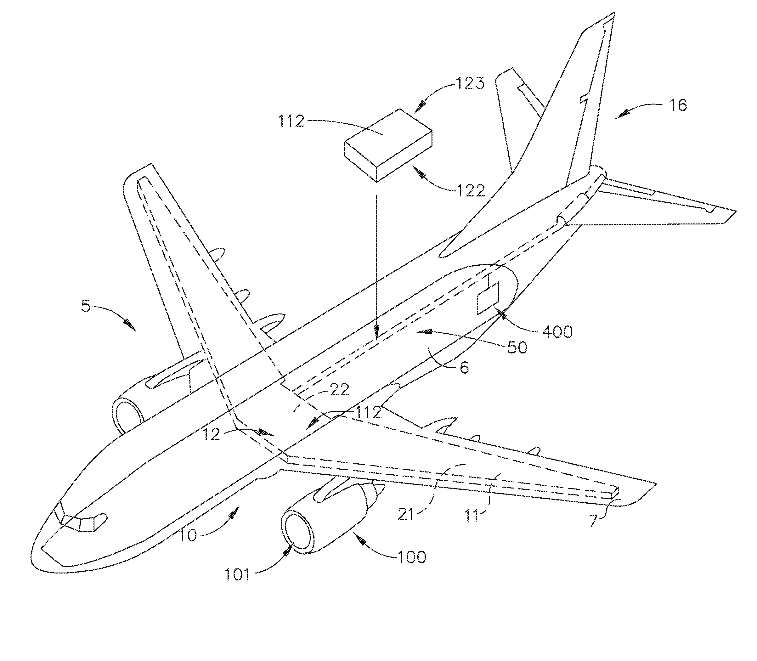
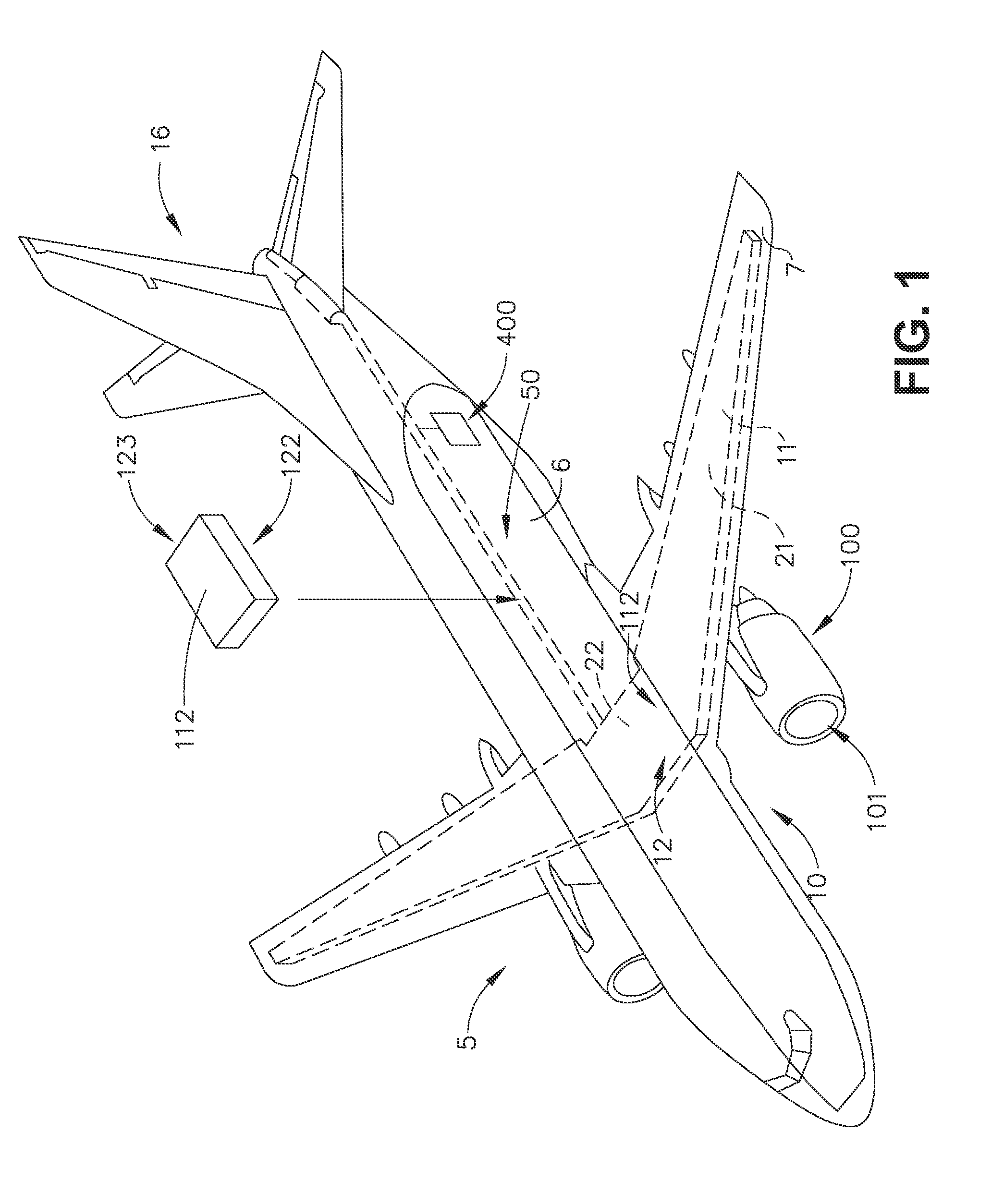
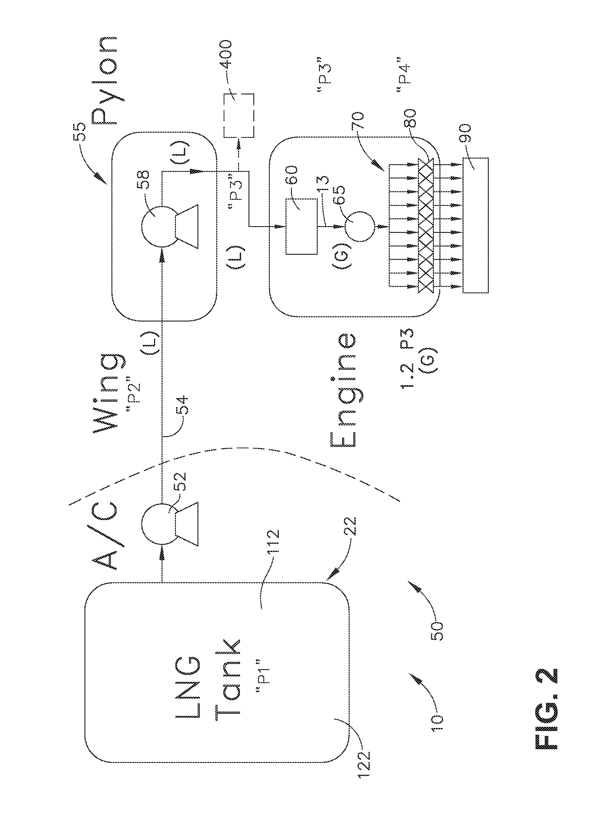
[0005]In one aspect, an embodiment of the invention relates to an aircraft, having a turbine engine having a bleed air output line, a cryogenic fuel system having a cryogenic fuel tank for storing cryogenic fuel and a supply line operably coupling the tank to the turbine engine, and an on board inert gas generating system (OBIGGS) fluidly coupled to the bleed air output and having a nitrogen rich stream output line and an oxygen rich stream output line.

[0006]In another aspect, an embodiment of the invention relates to a retrofit cryogenic fuel system for an aircraft having a cargo bay and a turbine engine fueled by the cryogenic fuel, including an evacuated enclosure configured to be received within the cargo bay, a cryogenic fuel tank located within the evacuated enclosure, and at least one vent line or fuel supply line fluidly coupled to the evacuated enclosure.

BRIEF DESCRIPTION OF THE DRAWINGS

[0007]The technology described herein may be best understood by reference to the followi...


PUM


Abstract

An aircraft having a turbine engine having a bleed air output line, a cryogenic fuel system having a cryogenic fuel tank for storing cryogenic fuel and a supply line operably coupling the tank to the turbine engine, and an on board inert gas generating system (OBIGGS) fluidly coupled to the bleed air output and having a nitrogen rich stream output line and an oxygen rich stream output line.

Description

CROSS REFERENCE TO RELATED APPLICATIONS[0001]This is a national stage application under 35 U.S.C. §371(c) of prior-filed, co-pending, PCT application serial number PCT / US2013 / 071836, filed on Nov. 26, 2013, which claims the benefit of U.S. Provisional Patent Application Nos. 61 / 746,930 and 61 / 747,171, both filed on Dec. 28, 2012. These applications are incorporated herein in their entirety.BACKGROUND OF THE INVENTION[0002]The technology described herein relates generally to aircraft systems, and more specifically to aircraft systems using dual fuels in an aviation gas turbine engine and a method of operating same.[0003]Certain cryogenic fuels such as liquefied natural gas (LNG) may be cheaper than conventional jet fuels. Current approaches to cooling in conventional gas turbine applications use compressed air or conventional liquid fuel. Use of compressor air for cooling may lower efficiency of the engine system.[0004]Accordingly, it would be desirable to have aircraft systems using...

Claims


Application Information

Patent Timeline
IPC IPC(8): B64D37/30F17C3/00
CPCF17C3/00B64D37/30F02C7/14F02C7/224F02C9/40F05D2260/213F05D2260/98Y02T50/40Y02T50/60Y02T90/40B64D37/32
Inventor EPSTEIN, MICHAEL JAYSTUMBO, PAUL BERNARDWEISGERBER, ROBERT HAROLD
Owner GENERAL ELECTRIC CO
Why Eureka
Try Eureka