
Configurations and methods of dewatering crude oil

Active Publication Date: 2015-12-03
FLUOR TECH CORP
View PDF6 Cites 4 Cited by
  • Summary
  • Abstract
  • Description
  • Claims
  • Application Information

AI Technical Summary

Benefits of technology

The patent describes a method for removing water from crude oil using a cyclone separator. The method involves flashing the crude oil in a flash vessel and then using the cyclone separator to remove the water as steam without causing foam carry-over into the vapor and liquid phases. The process can be carried out using a multi-cyclone separator and a control unit to regulate the temperature, flow rate, and pressure in the flash vessel. The technical effect of this invention is to provide a more efficient and effective way to remove water from crude oil.

Problems solved by technology

Separation of oil and water, and especially separation of water from heavy crudes is often challenging due to the relatively large volume, small differences in oil and water densities, and viscosity of the feed.
Some facilities add a light hydrocarbon diluent to facilitate separation oil and water; however, the use of diluent often adds significant cost and increases volumes and equipment size.
Unfortunately, such flashing typically generates substantial quantities of foam that must be sprayed down with a portion of the dewatered crude.
Thus, such approach requires one or more recycle pumps to move significant amounts of dewatered liquid for foam suppression and will so add to equipment and operational costs.
Preflash drums are a known source of foam problems where the light hydrocarbon vapors and the crude liquid tend to readily form bubbles.
While such solution is generally suitable for defoaming a liquid crude feed, it is limited to separating the light boiling hydrocarbons from the liquid feed that are both fed to the crude unit.
Therefore, even though various systems and methods for water removal from crude oil are known in the art, various disadvantages nevertheless remain.

Method used


Image

  • Configurations and methods of dewatering crude oil
  • Configurations and methods of dewatering crude oil
  • Configurations and methods of dewatering crude oil

Examples


Embodiment Construction

[0022]The following discussion provides example embodiments of the inventive subject matter. Although each embodiment represents a single combination of inventive elements, the inventive subject matter is considered to include all possible combinations of the disclosed elements. Thus if one embodiment comprises elements A, B, and C, and a second embodiment comprises elements B and D, then the inventive subject matter is also considered to include other remaining combinations of A, B, C, or D, even if not explicitly disclosed.

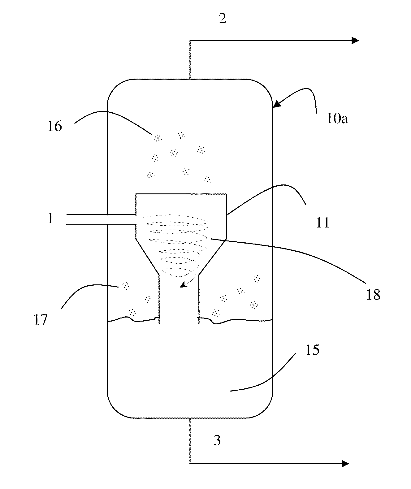
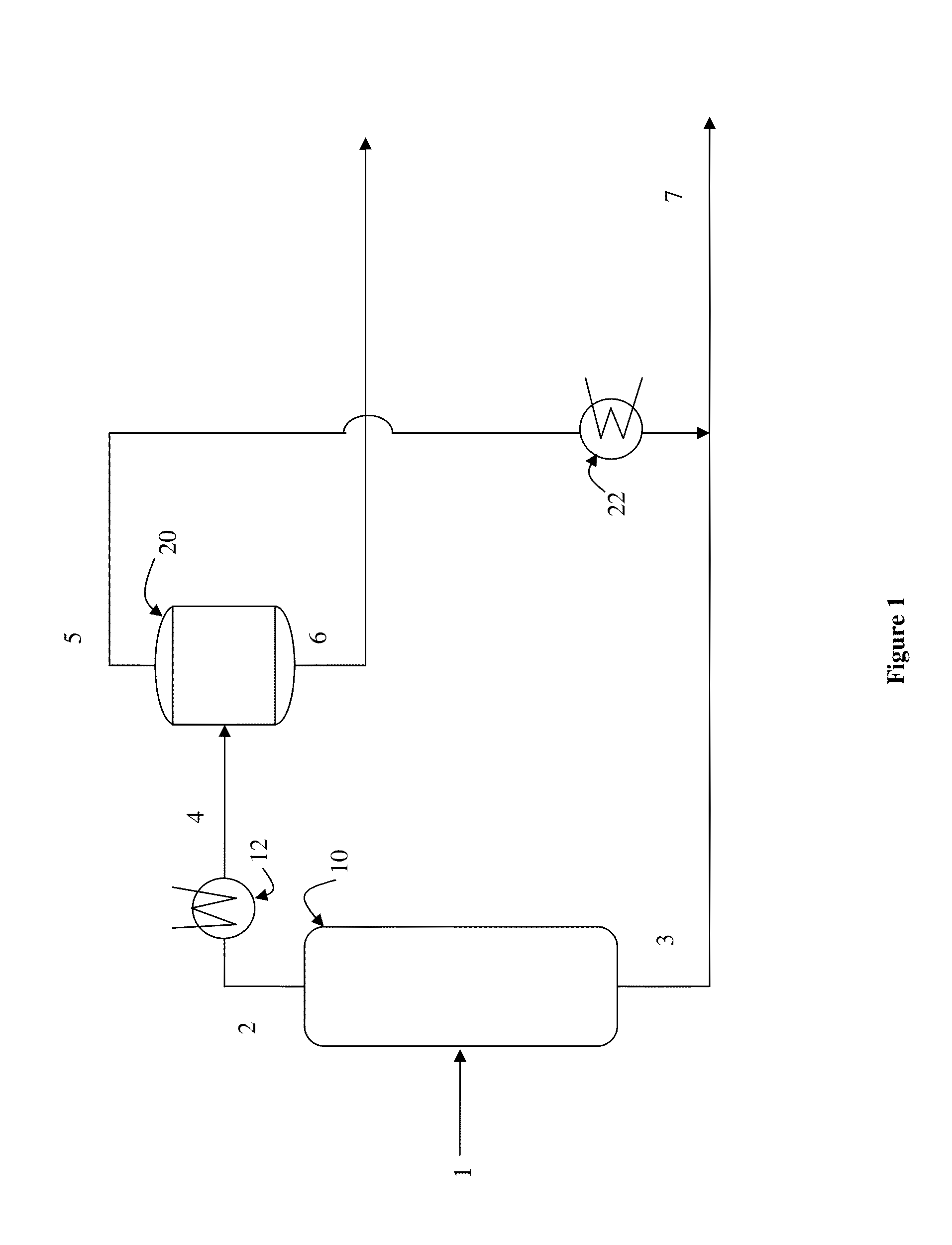
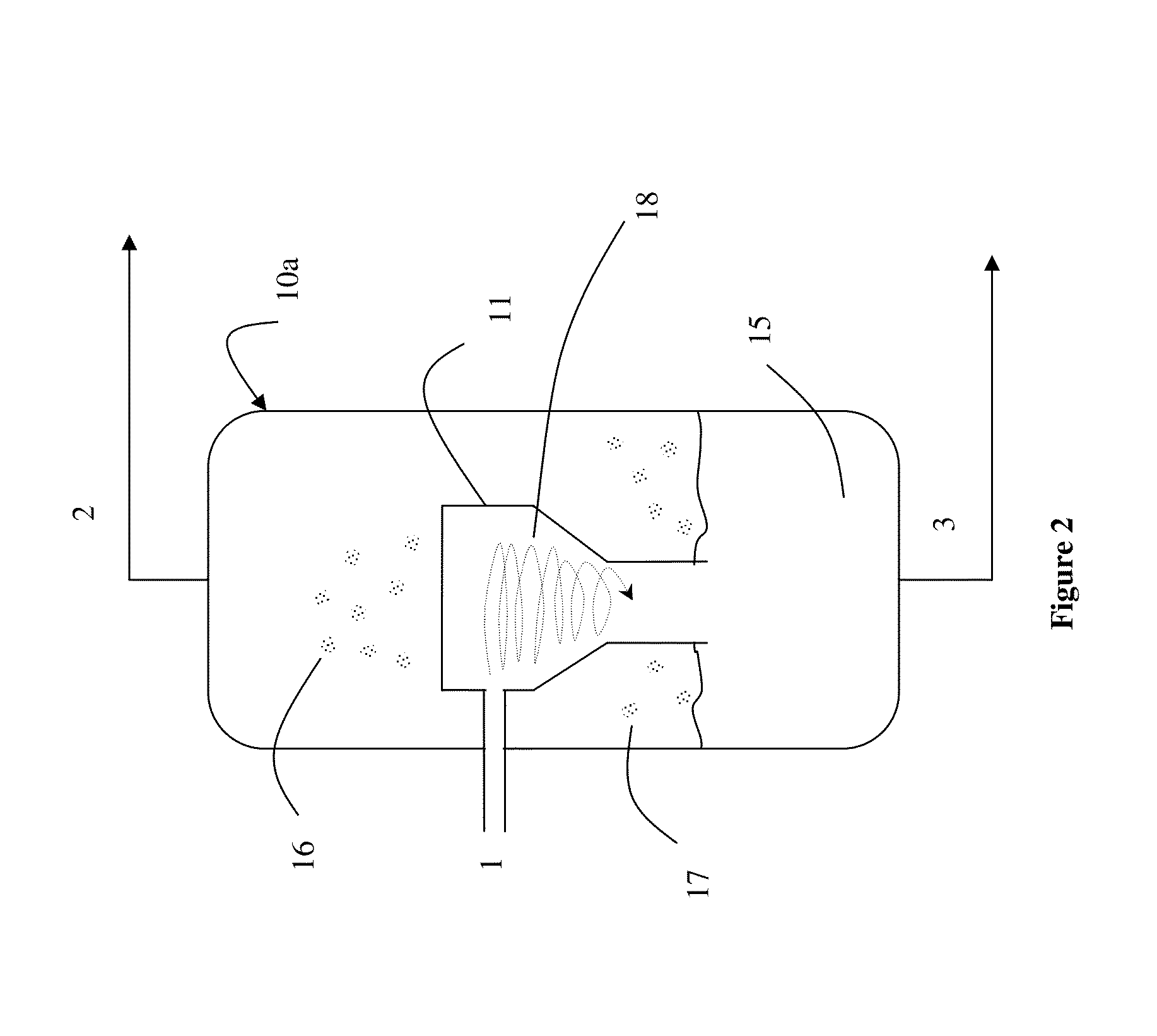
[0023]FIG. 1 shows a process for dewatering crude oil. Crude oil feed stream 1 enters flash vessel 10 at an inlet. Flash vessel 10 has a temperature and pressure that is selected such that at least 20%-40%, more preferably at least 70%, most preferably at least 90%, of the water in the crude oil is flashed into a steam vapor stream 2 exiting a top inlet of flash vessel 10. The liquid crude oil falls to the bottom of flash vessel and exits a bottom outlet as liqu...


PUM


Abstract

A process for dewatering crude oil is described. The process includes feeding crude oil onto a separation of a cyclone separator that is at least partially disposed in a flash vessel. The temperature are pressure in the flash vessel are selected such that at least 20% of the water contained in the crude oil is flashed from the crude oil as it moves on the separation surface of the cyclone separator. The flow rate and angle of the crude oil inlet is selected such that the crude oil moves across the separation surface as a film in a helical pattern, providing a substantial foaming-free manner. The vapor that is flashed from the crude oil exits the flash vessel at a top outlet and the liquid crude oil exits the flash vessel at a bottom outlet.

Description

[0001]This application claims the benefit of priority of U.S. provisional application Ser. No. 62 / 005164, filed on May 30, 2014.FIELD OF THE INVENTION[0002]The field of the invention is processing of crude oil, and especially as it relates to water removal from crude oil.BACKGROUND[0003]The background description includes information that may be useful in understanding the present invention. It is not an admission that any of the information provided herein is prior art or relevant to the presently claimed invention, or that any publication specifically or implicitly referenced is prior art.[0004]Separation of oil and water, and especially separation of water from heavy crudes is often challenging due to the relatively large volume, small differences in oil and water densities, and viscosity of the feed. Some facilities add a light hydrocarbon diluent to facilitate separation oil and water; however, the use of diluent often adds significant cost and increases volumes and equipment s...

Claims


Application Information

Patent Timeline
IPC IPC(8): C10G33/06C10G33/08C10G7/04
CPCC10G33/06C10G33/08C10G7/04
Inventor RODWELL, MORGAN CHARLES
Owner FLUOR TECH CORP
Learn More