Jacketed magnetic bearing and rotary machine comprising such a bearing

Inactive Publication Date: 2015-12-03
NUOVO PIGNONE SPA
View PDF5 Cites 6 Cited by
  • Summary
  • Abstract
  • Description
  • Claims
  • Application Information

AI Technical Summary

Benefits of technology

[0006]An object of the present invention is to remedy the above drawbacks while keeping the benefit of the principle of jacketing bearings

Problems solved by technology

Moreover, when the material of the jacket is a ferromagnetic material, it is no more necessary to have a thin jacket to protect the stator magnetic circuit: the jacket may have a larger thickness than a non-m

Method used


Image

  • Jacketed magnetic bearing and rotary machine comprising such a bearing
  • Jacketed magnetic bearing and rotary machine comprising such a bearing
  • Jacketed magnetic bearing and rotary machine comprising such a bearing

Examples


Embodiment Construction

[0027]The following detailed description of the exemplary embodiments refers to the accompanying drawings. The same reference numbers in different drawings identify the same or similar elements. Additionally, the drawings are not necessarily drawn to scale.

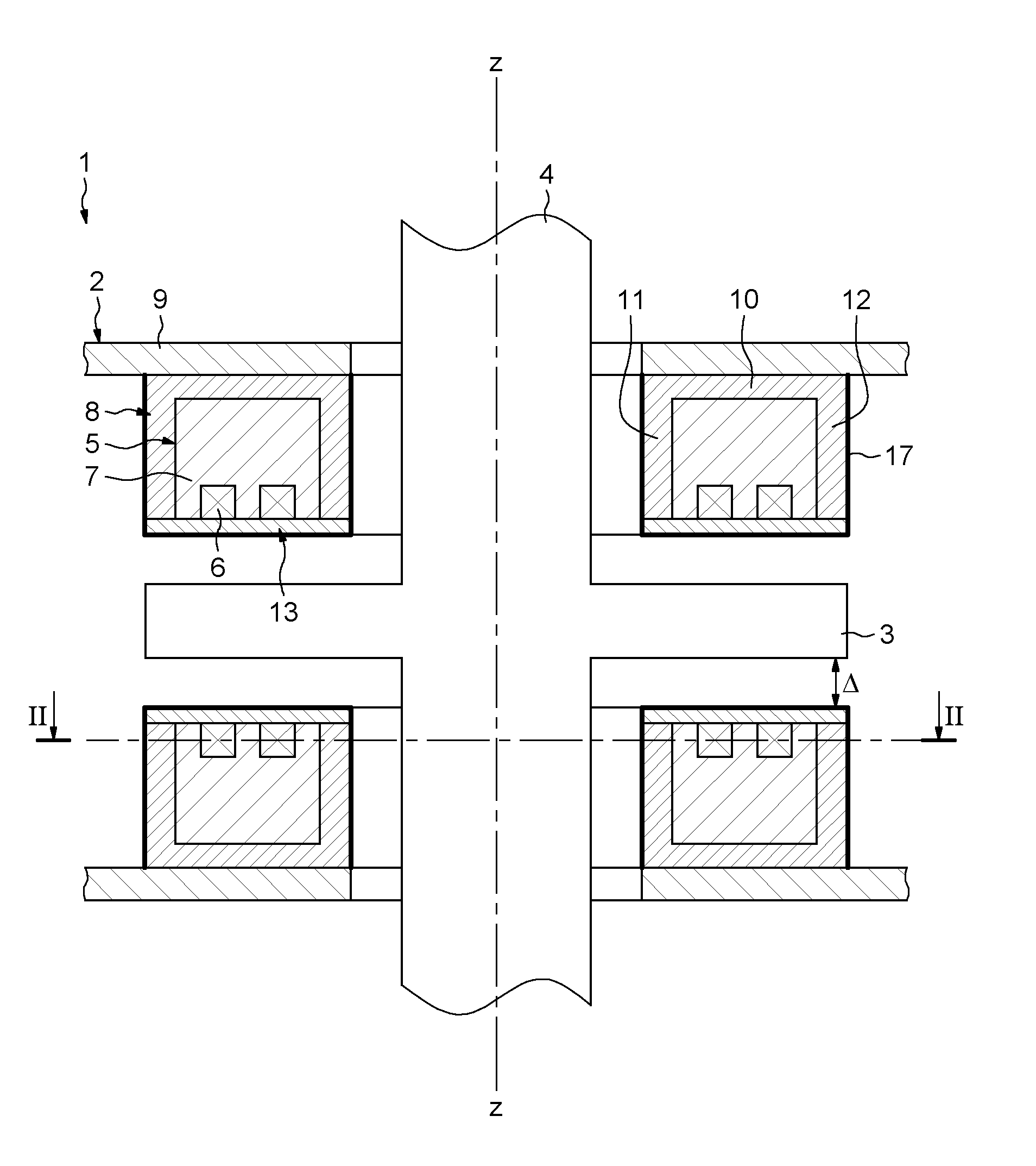
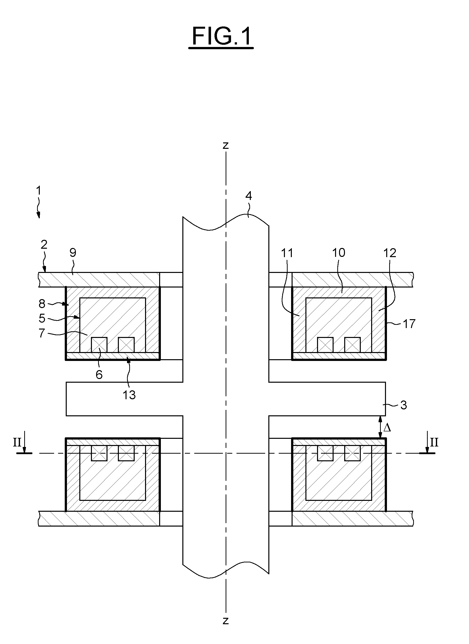
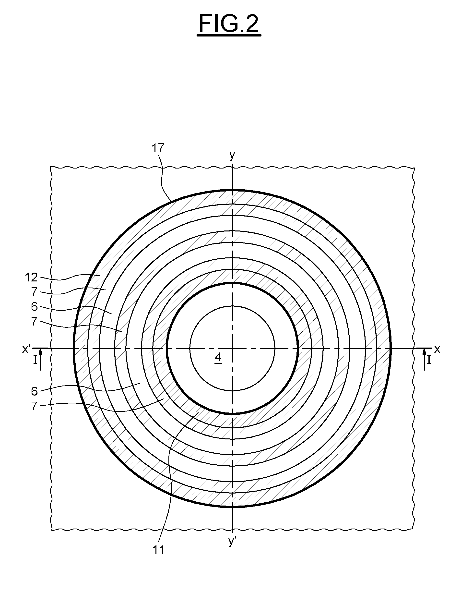
[0028]FIGS. 1 and 2 show a first embodiment of an axial jacketed magnetic bearing 1 of the present invention, for a rotary machine. The jacketed magnetic bearing 1 comprises a stator armature 2 and a rotor armature 3 in the form of a disk secured to a rotary shaft 4 of the rotary machine.

[0029]The stator armature 2 comprises a stator magnetic circuit 5 including, in conventional manner, one or more annular coils 6 and a ferromagnetic body 7. The ferromagnetic body 7 may be massive or it may be laminated locally. The stator magnetic circuit 5 is placed in a metallic annular support 8 that is itself secured to a stationary support device 9.

[0030]The stator magnetic circuit 5 is placed facing the rotor armature 3. The stator armature...


PUM


Abstract

A jacketed magnetic bearing for a rotary machine having a rotor. The jacketed magnetic bearing comprises a stator magnetic circuit secured to a stationary support device, the stator magnetic circuit comprising at least one coil and a ferromagnetic body placed in a metallic protective enclosure. Said protective enclosure comprises an annular support and an annular jacket, the annular support and the annular jacket being welded together. The annular jacket comprises magnetic material and is coated by a protective layer.

Description

BACKGROUND[0001]The embodiments disclosed relate generally to magnetic bearings for rotary machines having a rotor. In particular, the embodiments relate to magnetic bearings for rotary machines in which the rotor and the bearing are, in use, in contact with a fluid, for instance a gaseous atmosphere, that is corrosive, acid, or carrying particles. Some exemplary embodiments specifically relate to a rotary machine comprising such a magnetic bearing.[0002]Use of magnetic bearings to rotary machines is becoming more and more widespread, in particular in case of corrosive fluid. When the operating fluid of the machine in which the bearing operates is either acid, or corrosive or carrying particles, it is essential to protect the coils of the magnetic bearing and the associated means, by using anti-corrosion protection technologies. An example of such a technology is the jacketed bearing in which the stator portion of the bearing is protected by a metal jacket made of a material that do...

Claims


Application Information

Patent Timeline
IPC IPC(8): F16C32/04
CPCF16C32/0476F16C32/047F16C2300/42F16C2360/00F01D25/16F16C32/04
Inventor BIGI, MANUELEMEI, LUCIANOROMANELLI, MARCOFIORAVANTI, DUCCIOANSELMI, MARCO
Owner NUOVO PIGNONE SPA
Why Eureka
Try Eureka