Liquid crystal display device and electronic device

a liquid crystal display and electronic device technology, applied in non-linear optics, instruments, optics, etc., can solve the problems of shortening consuming the battery of long-time or repeated displays, and a large share of backlight power consumption, so as to reduce the power consumption of the display device, shorten the uptime of the portable information terminal, and consume the battery

Inactive Publication Date: 2015-12-03
SEMICON ENERGY LAB CO LTD
View PDF5 Cites 10 Cited by
  • Summary
  • Abstract
  • Description
  • Claims
  • Application Information

AI Technical Summary

Benefits of technology

[0008]Reducing power consumption of display devices for mobile applications, such as portable information terminals, is important. In transmissive liquid crystal display devices, backlights accounts for a large share of the power consumption. Therefore in a transmissive liquid crystal display device, long-time or repeated display rapidly consumes the battery and shortens the uptime of the portable information terminal. Reflective liquid cry...

Problems solved by technology

In transmissive liquid crystal display devices, backlights accounts for a large share of the power consumption.
Therefore in a transmissive liquid crystal display device, long-time or repeated display rapidly consumes the battery and shortens the uptime of the portable information terminal.
However, reflective l...

Method used


Image

  • Liquid crystal display device and electronic device
  • Liquid crystal display device and electronic device
  • Liquid crystal display device and electronic device

Examples


embodiment 1

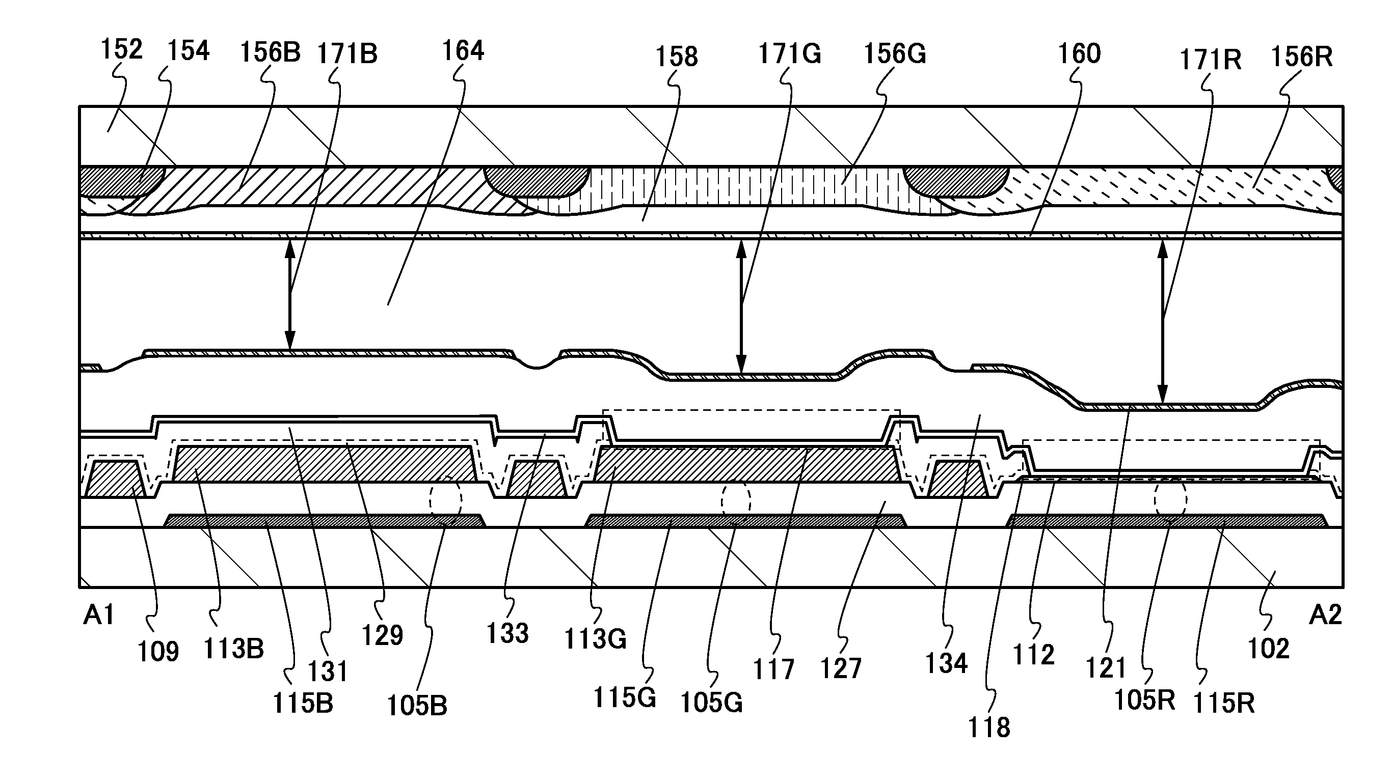
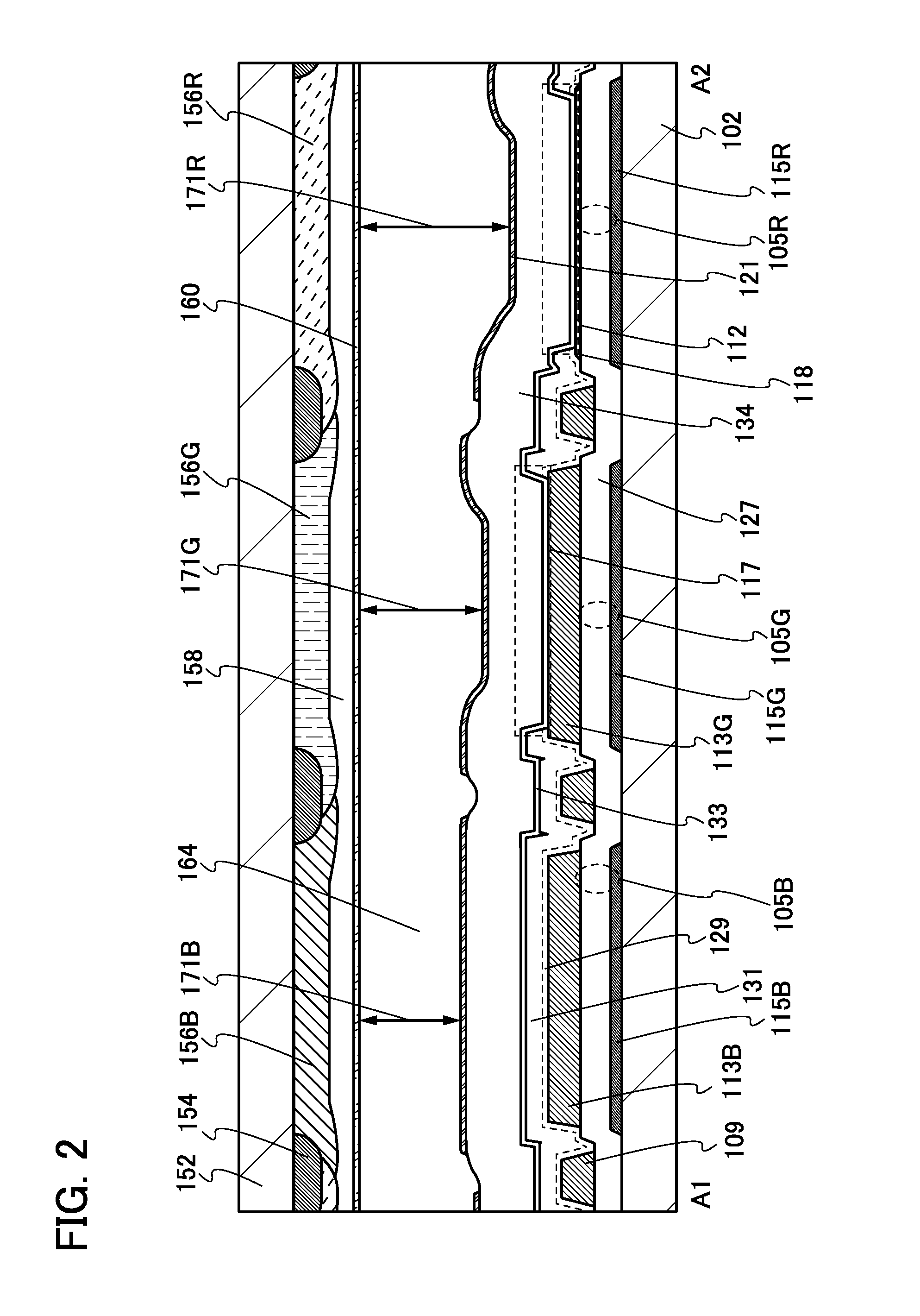
[0062]In this embodiment, a display device of one embodiment of the present invention is described with reference to FIGS. 1 to 4, FIGS. 5A to 5C, FIGS. 6A to 6C,

[0063]FIGS. 7A to 7C, FIGS. 8A to 8C, FIGS. 9A to 9C, FIGS. 10A to 10C, FIGS. 11A to 11C, and FIGS. 12A to 12C, FIGS. 13A and 13B, FIG. 14, and FIGS. 20 and 21.

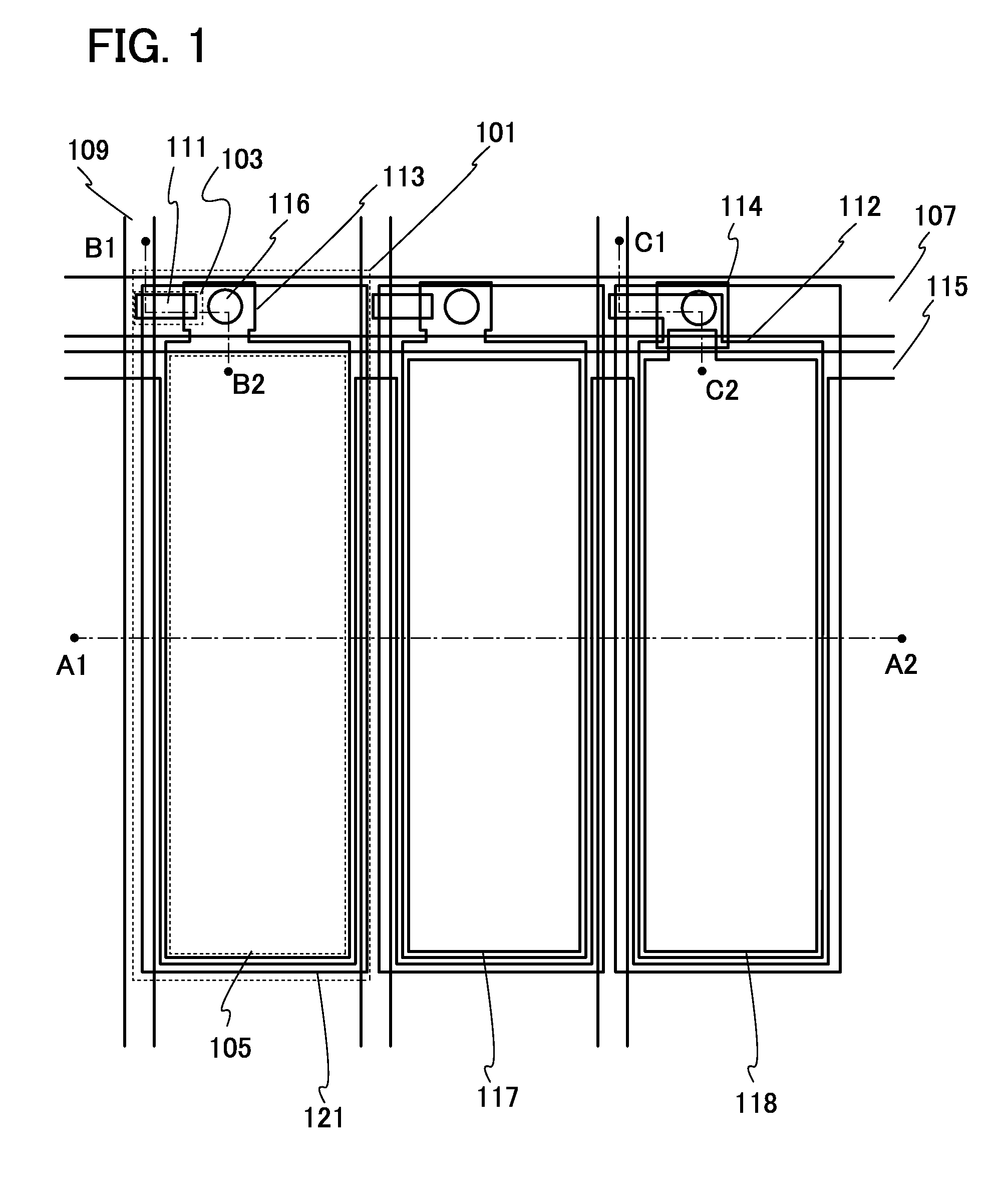
[0064]FIG. 1 is a top view of a pixel and its periphery of a display device. Note that in the top view illustrated in FIG. 1, some components are not illustrated in order to avoid complexity of the drawing.

[0065]In FIG. 1, a pixel 101 is provided in a region defined by a scan line 107, a data line 109, and a capacitor line 115. The scan line 107 extends in the direction substantially perpendicular to the data line 109 (in the horizontal direction in the drawing). The data line 109 extends in the direction substantially perpendicular to the scan line 107 (in the vertical direction in the drawing). The capacitor line 115 extends in the direction substantially parallel ...

modification example 1

[0151]Here, a cross-sectional view of a modification example of the pixels and their periphery in the display device illustrated in FIG. 2 is described with reference to FIG. 14.

[0152]The cross-sectional view of the pixels and their periphery of the display device in FIG. 14 is different from that in FIG. 2 in that a semiconductor layer 172B and a semiconductor layer 172G are provided under the conductive layer 113B and the conductive layer 113G, respectively.

[0153]The semiconductor layers 172B and 172G and the conductive layers 113B and 113G may be processed with different masks, or with one mask through two-step etching treatment by using a half-tone mask or a gray-tone mask. The use of a half-tone mask or a gray-tone mask can reduce the number of masks by one.

modification example 2

[0154]By combining the structure in FIG. 2 with that in FIG. 14, five types of cell gaps can be obtained to correspond to four or five colors.


PUM


Abstract

A reflective liquid crystal display device having improved contrast is provided. A reflective liquid crystal display device having improved color reproducibility is provided. A reflective liquid crystal display device having low power consumption is provided. A cell gap is adjusted for each color by devising the positions of a conductive layer and an insulating layer under a reflective electrode. A capacitor is placed under the reflective electrode, and one of the electrodes is a common electrode while the other thereof is a conductive layer or a metal oxide layer. By leaving or removing an insulating layer over the other electrode, the cell gap can be adjusted.

Description

BACKGROUND OF THE INVENTION[0001]1. Field of the Invention[0002]One embodiment of the present invention relates to a reflective liquid crystal display device and an electronic device including the liquid crystal display device.[0003]Note that one embodiment of the present invention is not limited to the above technical field. The technical field of one embodiment of the invention disclosed in this specification and the like relates to an object, a method, or a manufacturing method. In addition, one embodiment of the present invention relates to a process, a machine, manufacture, or a composition of matter. Specifically, examples of the technical field of one embodiment of the present invention disclosed in this specification include a semiconductor device, a display device, a liquid crystal display device, a light-emitting device, a lighting device, a power storage device, a memory device, a method of driving any of them, and a method of manufacturing any of them.[0004]2. Descriptio...

Claims


Application Information

Patent Timeline
IPC IPC(8): G02F1/1335G02F1/1333
CPCG02F1/133345G02F1/133553G02F1/133371G02F1/136213G02F2203/02
Inventor KUBOTA, DAISUKE
Owner SEMICON ENERGY LAB CO LTD
Why Eureka
Try Eureka