Electro-mechanical dynamo for c and d battery replacement

a technology of electro-mechanical dynamo and battery replacement, which is applied in the direction of mechanical equipment, two-wire dc circuits, machines/engines, etc., can solve the problems of no prior art that provides packaging of electro-mechanical power generating devices, no prior art that provides multiple voltage regulated power sources, and no performance loss. , to achieve the effect of reducing chemical waste, reducing waste, and reducing the loss of performan

Active Publication Date: 2015-12-03
NELSON BRADLEY
View PDF3 Cites 3 Cited by
  • Summary
  • Abstract
  • Description
  • Claims
  • Application Information

AI Technical Summary

Benefits of technology

[0012]The present invention will have power available for weeks or months after the device has been installed and can be repeatedly rewound without loss of performance. The following detailed description of the drawings and their functions will clearly illustrate how this unique device can benefit the environment by reducing the chemical waste created by the disposal of thousands of electro-chemical batteries.
[0013]An object of this invention is to provide a reliable power source for electronic devices that are presently using electro-chemical batteries. Advances in electronics, metallurgy, and magnetics have made it possible to obtain the power density required to power most devices such as but not limited to flashlights, radios, and USB powered devices or for charging cell phones and PDA's.
[0014]An object of this invention is to have power available for weeks or months after the device has been installed, this is achieved in three ways. The first way is by having a unique solenoid activated clutch mechanism that locks the main spring and generator when no power is applied to the solenoid conserving the charge on the storage capacitor. The second way is the incorporation of very high off state resistance FET transistors and nano-powered voltage threshold detector Integrated Circuits in the electronic circuit to further conserve the charge on the storage capacitor. The third way is the incorporation of a high microfarad value storage capacitor in the electronic circuit to extend the time period between the activation of the generator to maintain the standby voltage.

Problems solved by technology

There is no prior art that incorporates a mainspring to store energy for extended periods of time coupled with a unique clutch and solenoid mechanism to power a generator on demand only when an external load is detected.
There is no prior art that provides packaging of an electro-mechanical power generating device with the form and dimensions of two standard C or D size flashlight batteries that can be installed into and power devices currently using electro-chemical batteries.
There is no prior art that provides multiple voltage regulated power sources that are independently activated only when a load is detected from external devices to extend the time power will be available.
There is no prior art that reverses the function of a generator using it as a motor for the purpose of winding a main spring to store power.
Additionally current hand crank devices do not have power density or the ability to retain available power for long periods of time or have the ability to be used in devices designed for standard C and D type batteries.

Method used


Image

  • Electro-mechanical dynamo for c and d battery replacement
  • Electro-mechanical dynamo for c and d battery replacement
  • Electro-mechanical dynamo for c and d battery replacement

Examples


Embodiment Construction

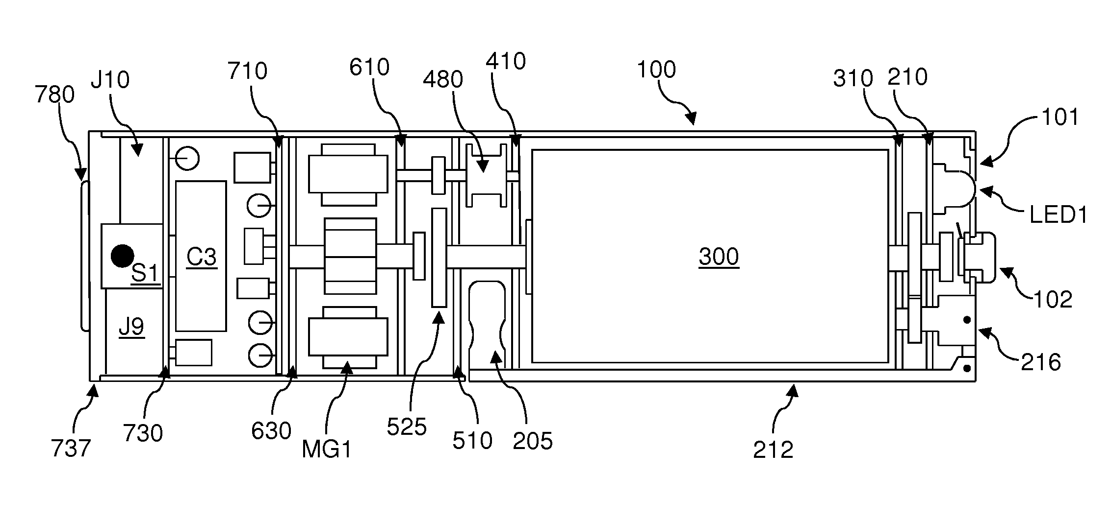
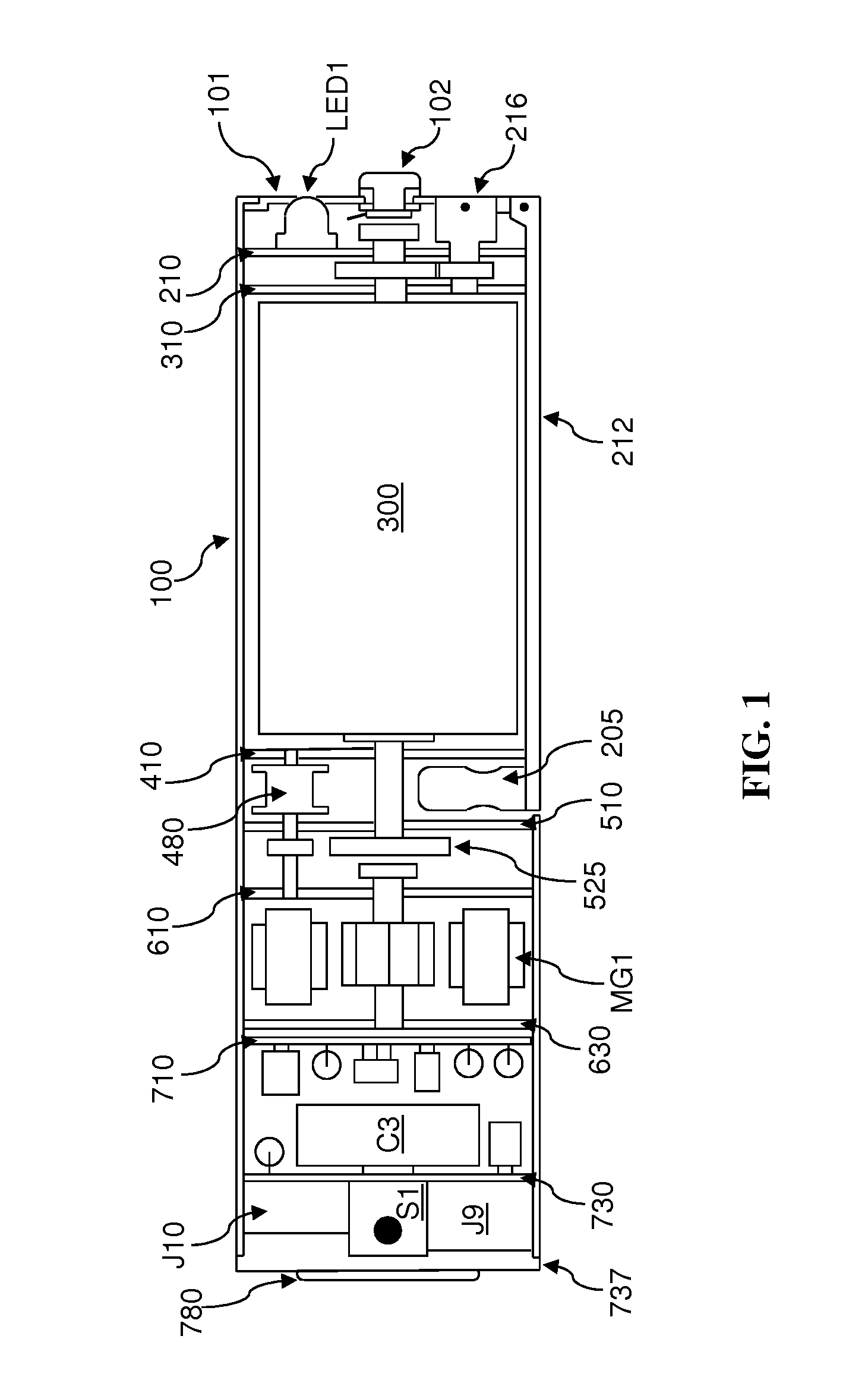
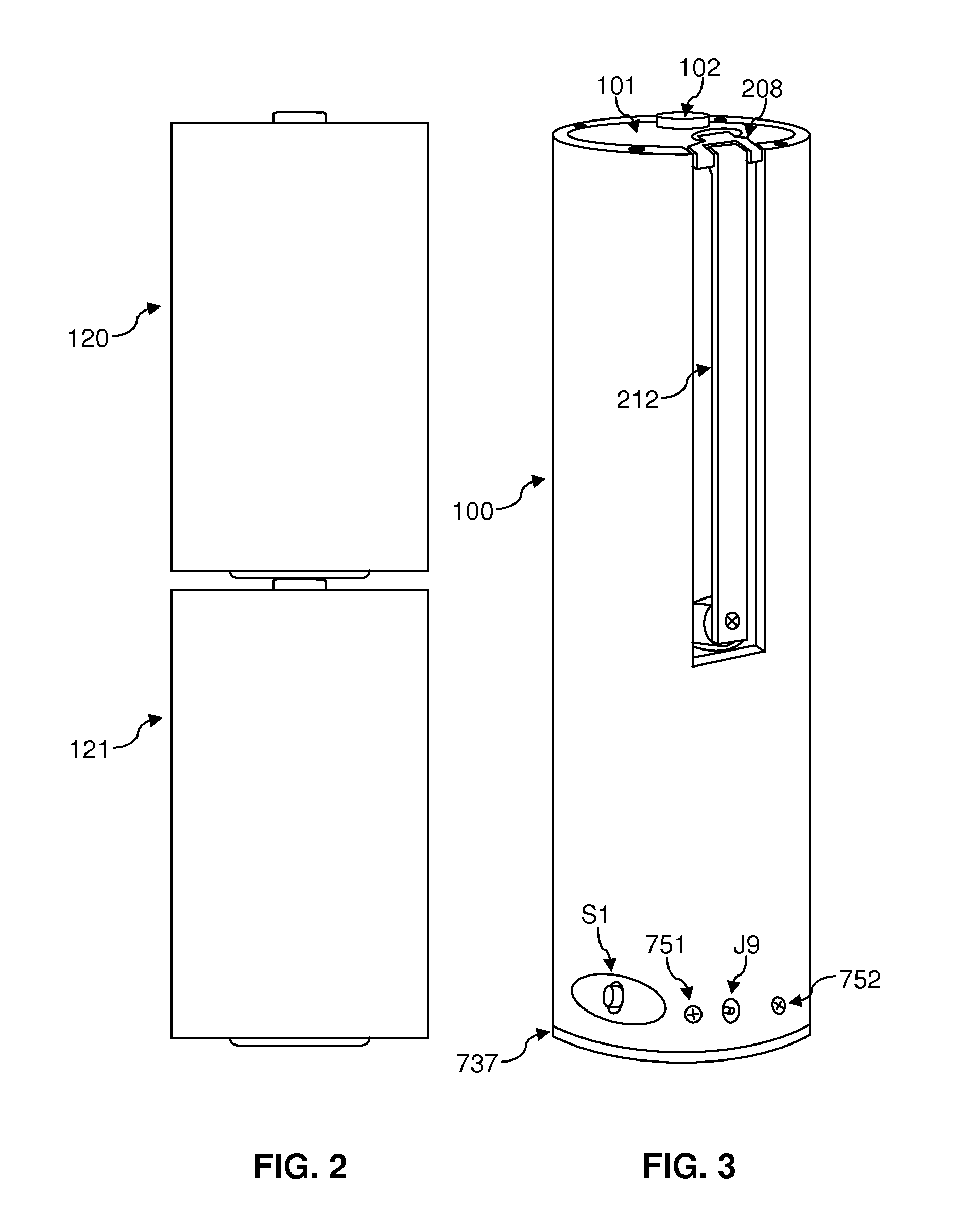
[0231]The following detailed description is directed to certain specific embodiments of the invention. However, the invention can be embodied in a multitude of different ways as defined and covered by the claims and their equivalents. In this description, reference is made to the drawings wherein like parts are designated with like numerals throughout.

[0232]Unless otherwise noted in this specification and the claims will have the meanings normally ascribed to these terms by those skilled in the art.

[0233]Unless the context clearly requires otherwise, throughout the description and the claims, the words “comprise”, “comprising” and the like are to be construed in an inclusive sense as opposed to an exclusive sense; that is to say, in a sense of “including, but not limited to”. Words using the singular or plural number also include the plural or singular number, respectively. Additionally, the words “herein”, “above”, “below”, and words of similar import, when used in this application...


PUM


Abstract

A self-contained electro-mechanical device incorporating a hand crank wound main spring mechanism coupled with gears to a rotating magnet inside an iron core with wound copper wire for the purpose of generating electricity. An external AC adaptor can use the generator as a motor to wind the main spring without the need to use the hand crank. An internal electronic circuit is connected to the motor/generator and mechanically coupled using a unique solenoid and clutch mechanism to prevent the main spring from turning until an external load is detected. When packaged in the form of two standard C or D size batteries this invention can be installed into devices currently using electro-chemical batteries. An internal LED light enables the device to be used as a self-contained flashlight. A mini USB connector is incorporated for charging cell phones and powering numerous devices compatible with USB power.

Description

BACKGROUND OF THE INVENTION[0001](1) Field of the Invention[0002]This invention generally relates an electro-mechanical device for the purpose of generating electricity by means of a main spring mechanism which can be wound by hand or power derived by an external AC adaptor employing a combination motor / generator. More particularly the invention provides a means to retain its potential to provide power when needed for long periods of time by implementation of a unique solenoid and clutch mechanism. Additionally this embodiment of the invention is packaged in the form of two standard C or D sized batteries stacked one on top of the other allowing the invention to be installed into devices normally using electro-chemical batteries. Additionally this invention provides a means to provide multiple voltage sources including USB power for different applications and can also be used as a self-contained LED flashlight.[0003](2) Description of the Related Art[0004]There are devices that inco...

Claims


Application Information

Patent Timeline
Patent Type & Authority Applications(United States)
IPC IPC(8): H02K7/18H02J1/06
CPCH02K7/1853Y10T307/406H02J1/06H02K7/1861
Inventor NELSON, BRADLEY
Owner NELSON BRADLEY
Why Eureka
Try Eureka