Reconfigurable fully-connected bidirectional hybrid beamforming transceiver
a beamforming transceiver and fully connected technology, applied in the field of reconfigurable fully connected bidirectional hybrid beamforming transceivers, can solve the problems of inability to operate in prior art beamforming devices, inability to meet the requirements of spectral efficiency, so as to achieve efficient scaling, improve energy efficiency, and achieve the effect of improving the efficiency of operation
- Summary
- Abstract
- Description
- Claims
- Application Information
AI Technical Summary
Benefits of technology
Problems solved by technology
Method used
Image
Examples
first embodiment
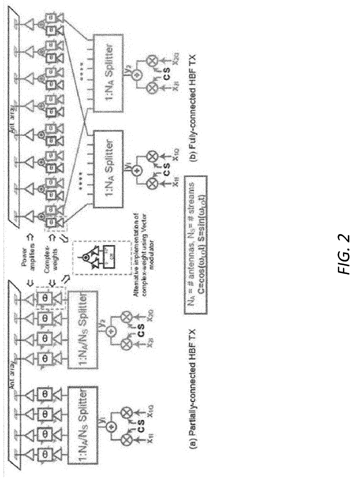
[0021]the FC-HBF transmitter described herein is illustrated in View (b) of FIG. 2. A PC-HBF transmitter is shown in View (a) of FIG. 2 for comparison. In the FC-HBF transmitter, independent baseband data streams are upconverted using a complex-quadrature mixer. Outputs y1 and y2 are then split into N identical paths. Complex-valued weights are applied to each upconverted streams in polar form using a combination of a programmable phase shifter and a programmable gain amplifier. In the FC-HBF transmitter, weighted signals from the individual streams are combined and then input to power amplifiers (PA). Each PA drives a single antenna element with the requisite amount of power. Implementation of the phase-shifters poses several difficulties including large size, high insertion loss, relatively low port impedances, limited bandwidth and non-linear control characteristics.
[0022]A second embodiment of the FC-HBF transmitter uses a similar architecture to the first embodiment but realize...
third embodiment
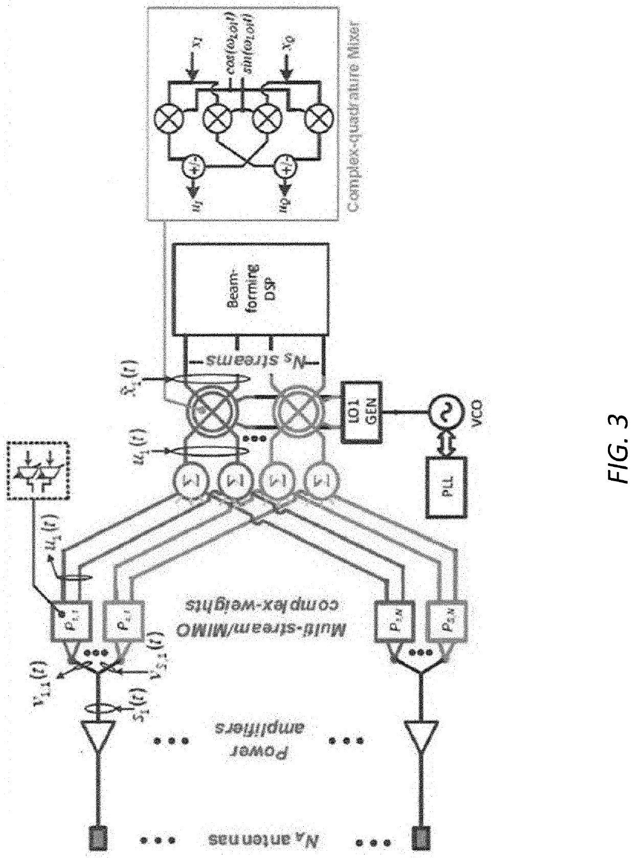
[0023]A third embodiment, which overcomes all the aforementioned challenges, is illustrated in FIG. 3. Here, each baseband stream is upconverted using a complex-quadrature mixer (shown schematically in the inset of FIG. 3) to the RF carrier frequency and split into N paths. Per-stream and per-antenna complex-valued weights (Ps,k's) are applied using a pair (Pk's) of programmable-gain amplifiers. Weighted signals from all upconverted streams are then combined and input to PA's which drive the antenna elements.
[0024]The operation of the third embodiment can be described mathematically as follows. We represent the sth baseband stream by its baseband envelope {tilde over (x)}s(t)=(xs,I+jxs,Q). The quadrature upconverted signal u(t) in the sth stream can be written as:
us(t)=us,I+jus,Q=x~s(t)ejωRFt=(xs,I+jxs,Q)ejωRFt=(xs,IC-xs,QS)+j(xs,IS-xs,QC)(1)
[0025]For the sth stream and the kth antenna, the objective is to apply a programmable complex-valued weight Ps,k=PRe-s,k+jPIm-s,k to the envel...
second embodiment
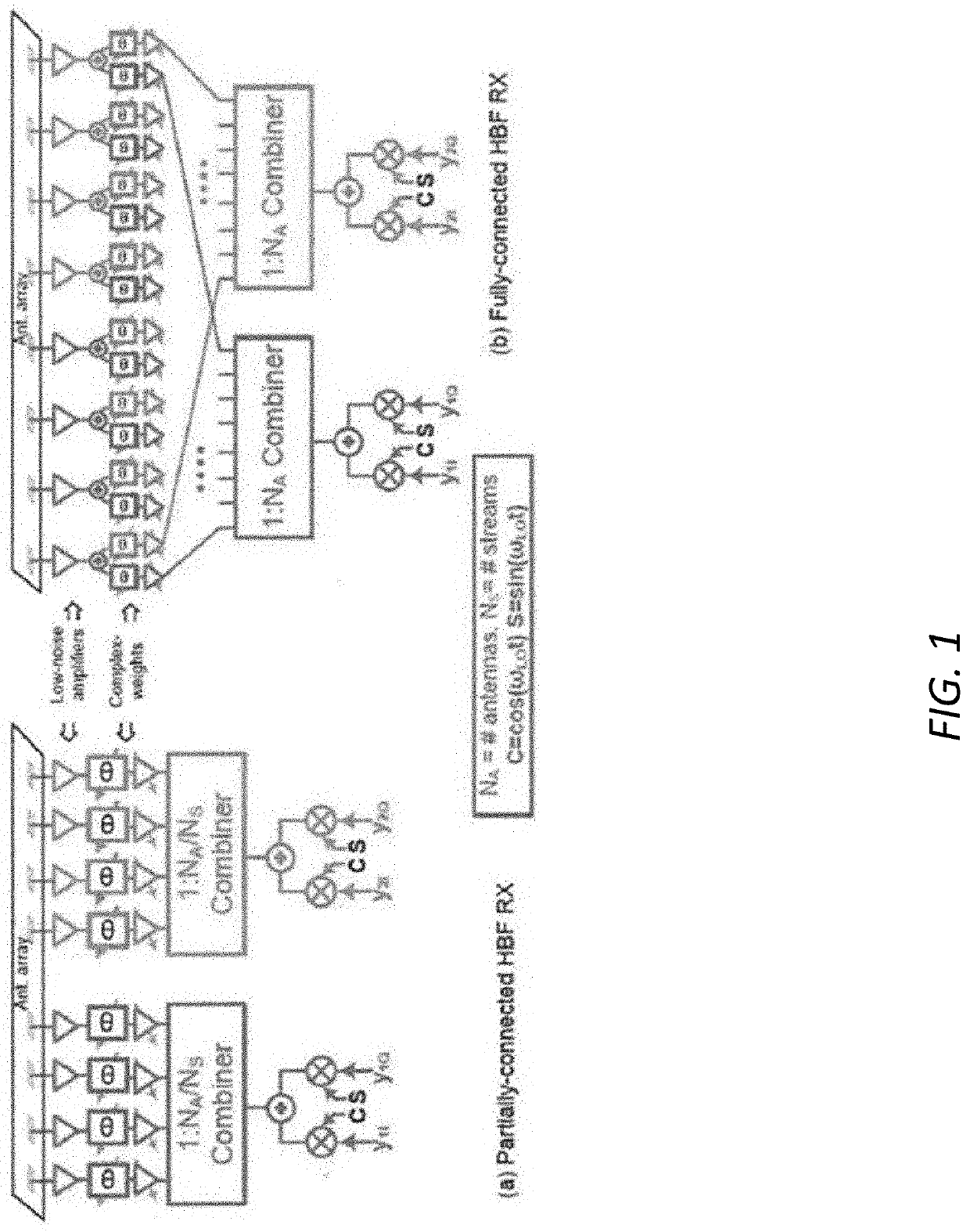
[0028]The FC-HBF transmitter described above can be combined with the FC-HBF receiver architecture described in U.S. patent application Ser. No. 16 / 163,374 to realize a bi-directional FC-HBF transceiver. A schematic illustration of a transceiver based on the invention as described above is shown in FIG. 4. Here, the programmable-gain amplifiers used to realize the complex-valued weights are designed such that they can be configured to pass signals either in the forward direction only or in the reverse direction only.
Carrier Aggregation
[0029]Due to the availability of multiple downconversion chains, HBF's inherently able to support carrier aggregation (where independent data can be received at multiple frequencies), thereby increasing data rate. However, in a PC-HBF, a separate sub-array is required for each aggregated carrier. On the other hand, in a FC-HBF, the same antenna array can be used to transmit or receive several aggregated carriers. Specifically, an FC-HBF can support agg...
PUM
 Abstract
Description
Claims
Application Information
 - R&D
- Intellectual Property
- Life Sciences
- Materials
- Tech Scout
- Unparalleled Data Quality
- Higher Quality Content
- 60% Fewer Hallucinations
Browse by: Latest US Patents, China's latest patents, Technical Efficacy Thesaurus, Application Domain, Technology Topic, Popular Technical Reports.
© 2025 PatSnap. All rights reserved.Legal|Privacy policy|Modern Slavery Act Transparency Statement|Sitemap|About US| Contact US: help@patsnap.com


