Alarm system with acousto-optic early-warning design
An alarm system, acousto-optic technology, applied in the fields of optics, acoustics, and electronic science, can solve the problems of inability to play early warning, unusable, too simple design, etc., and achieve the effect of low power consumption, simple structure, scientific and reasonable working principle
- Summary
- Abstract
- Description
- Claims
- Application Information
AI Technical Summary
Problems solved by technology
Method used
Image
Examples
Embodiment 1
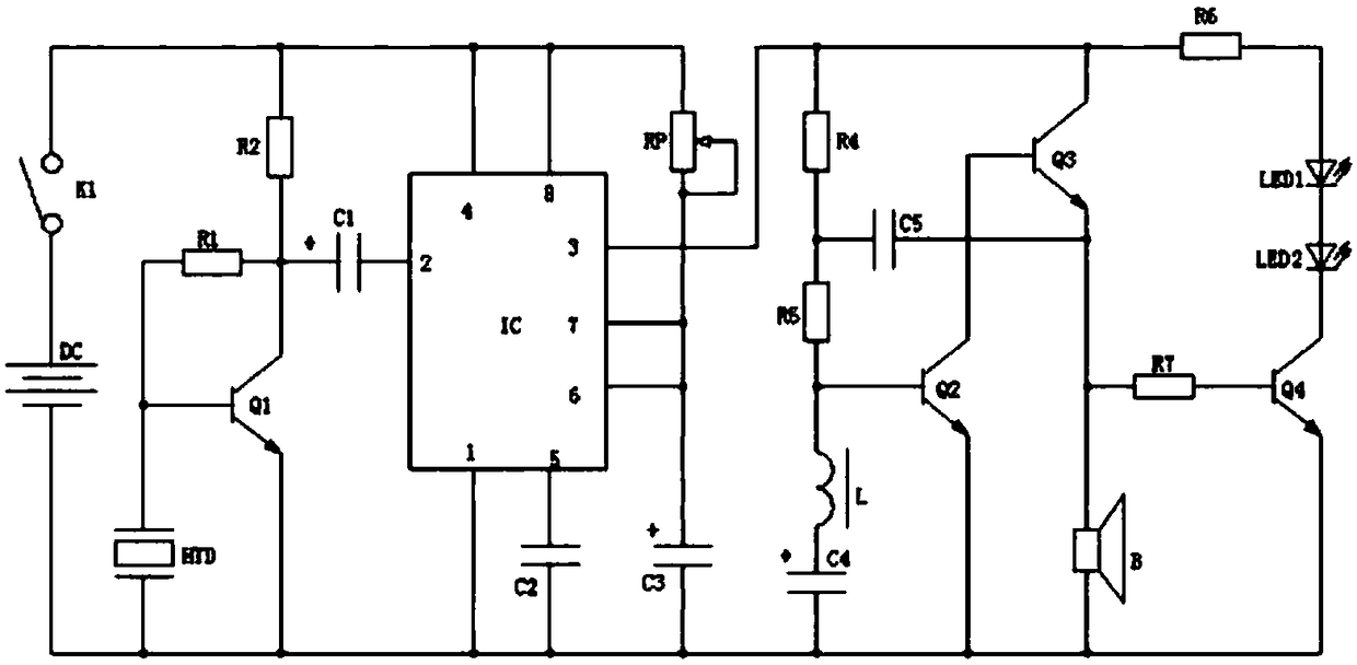
[0025] An alarm system designed with sound and light early warning, designed a relatively simple structure, but with early warning and alarm function, using sound and light synchronous reminder to alarm system, when the sound is not enough to expel pests or pests in the protected area In the case of small animals, the abruptness of light can be used to scare away pests or small animals. Its scientific and reasonable working principle and practical functionality are loved by the majority of users, such as figure 1 As shown, the following structure is specially provided: including a light early warning circuit and a sound early warning circuit, the light early warning circuit is connected to the sound early warning circuit; the light early warning circuit includes a resistor R6, a light emitting diode LED1, a light emitting diode LED2, a resistor R7 and an NPN Transistor Q4, the sound warning circuit is respectively connected to the first end of the resistor R6 and the first end ...
Embodiment 2
[0027] This embodiment is further optimized on the basis of the above-mentioned embodiments. Further, in order to better realize the present invention, sound mode can be used for early warning, such as figure 1 As shown, the following structure is particularly provided: the sound warning circuit is mainly composed of a piezoelectric conversion circuit, a time base circuit, and an audio processing circuit, the piezoelectric conversion circuit is connected to the time base circuit, and the time base circuit is connected to the audio processing circuit. Circuit; the first end of the resistor R6 and the first end of the resistor R7 are both connected to the audio processing circuit.
Embodiment 3
[0029] This embodiment is further optimized on the basis of the above-mentioned embodiments, further to better realize the present invention, such as figure 1 As shown, the following structure is particularly provided: the piezoelectric conversion circuit includes a piezoelectric ceramic buzzer HTD, an NPN transistor Q1, a resistor R2 and an electrolytic capacitor C1, and the first ends of the piezoelectric ceramic buzzer HTD are respectively Connect the second end of the resistor R1 to the base of the NPN transistor Q1, the second end of the piezoelectric ceramic buzzer HTD is connected to the emitter of the NPN transistor Q1; the collector of the NPN transistor Q1 is respectively connected to the resistor R1 The second end, the first end of the resistor R2 are connected to the positive pole of the electrolytic capacitor C1, and the first end of the resistor R2, the negative pole of the electrolytic capacitor C1 and the emitter of the NPN transistor Q1 are all connected to the...
PUM
 Abstract
Description
Claims
Application Information
 - R&D
- Intellectual Property
- Life Sciences
- Materials
- Tech Scout
- Unparalleled Data Quality
- Higher Quality Content
- 60% Fewer Hallucinations
Browse by: Latest US Patents, China's latest patents, Technical Efficacy Thesaurus, Application Domain, Technology Topic, Popular Technical Reports.
© 2025 PatSnap. All rights reserved.Legal|Privacy policy|Modern Slavery Act Transparency Statement|Sitemap|About US| Contact US: help@patsnap.com

