Method and apparatus for determining a rotor position and rotation speed of an electrical machine

a technology of rotor position and rotation speed, which is applied in the direction of electronic commutation motor control, motor/generator/converter stopper, dynamo-electric converter control, etc., can solve the problem that the brushes are not suitable for operation

Active Publication Date: 2015-12-03
ROBERT BOSCH GMBH
View PDF3 Cites 8 Cited by
  • Summary
  • Abstract
  • Description
  • Claims
  • Application Information

AI Technical Summary

Benefits of technology

[0006]The object of the present invention is to provide a method and an apparatus with which the rotation speed and / or the rotor position of an electric motor can be detected in an improved manner with brushes which commutate in an offset manner.
[0012]This results in the main order of the current ripple, which main order is generally suppressed by the brushes which commutate in an offset manner, being suppressed to a lesser extent at the frequency which is determined by the number of commutator laminations and the actual rotation speed. In this way, a proportion of the current ripple with a frequency of the main order remains in the frequency range determined by the number of commutator laminations, so that it remains suitable for evaluation in respect of a rotation speed and / or a rotor position. In this way, the rotation speed and / or the rotor position of electric motors can be detected using conventional motor controllers, without it being necessary to dispense with the advantages provided by the commutation with offset brushes.
[0013]The non-uniform design of the stator poles in particular leads to the induced voltages in the rotor coils which commutate at the positive and negative brushes being different. The current profiles at the positive and negative brushes are likewise different as a result and the phase-offset superimposition of the current profiles which is caused by the alternating commutation therefore leads to reduced weakening of the current ripple in the main order of the frequency which is determined by the number of commutator laminations.

Problems solved by technology

On account of the low current ripple, in particular in the order of the number of commutator laminations, said brushes are not suitable for operation on controllers which use the current ripple to detect the rotation speed of the electric motor and / or the rotor position.

Method used


Image

  • Method and apparatus for determining a rotor position and rotation speed of an electrical machine
  • Method and apparatus for determining a rotor position and rotation speed of an electrical machine
  • Method and apparatus for determining a rotor position and rotation speed of an electrical machine

Examples


Embodiment Construction

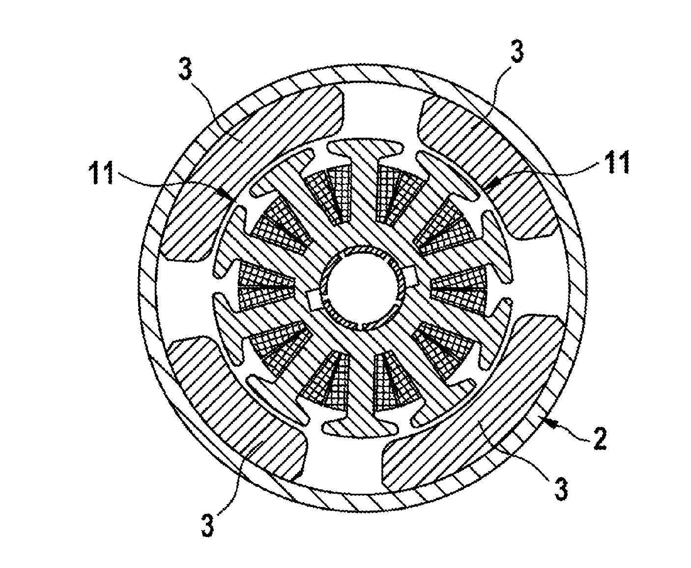
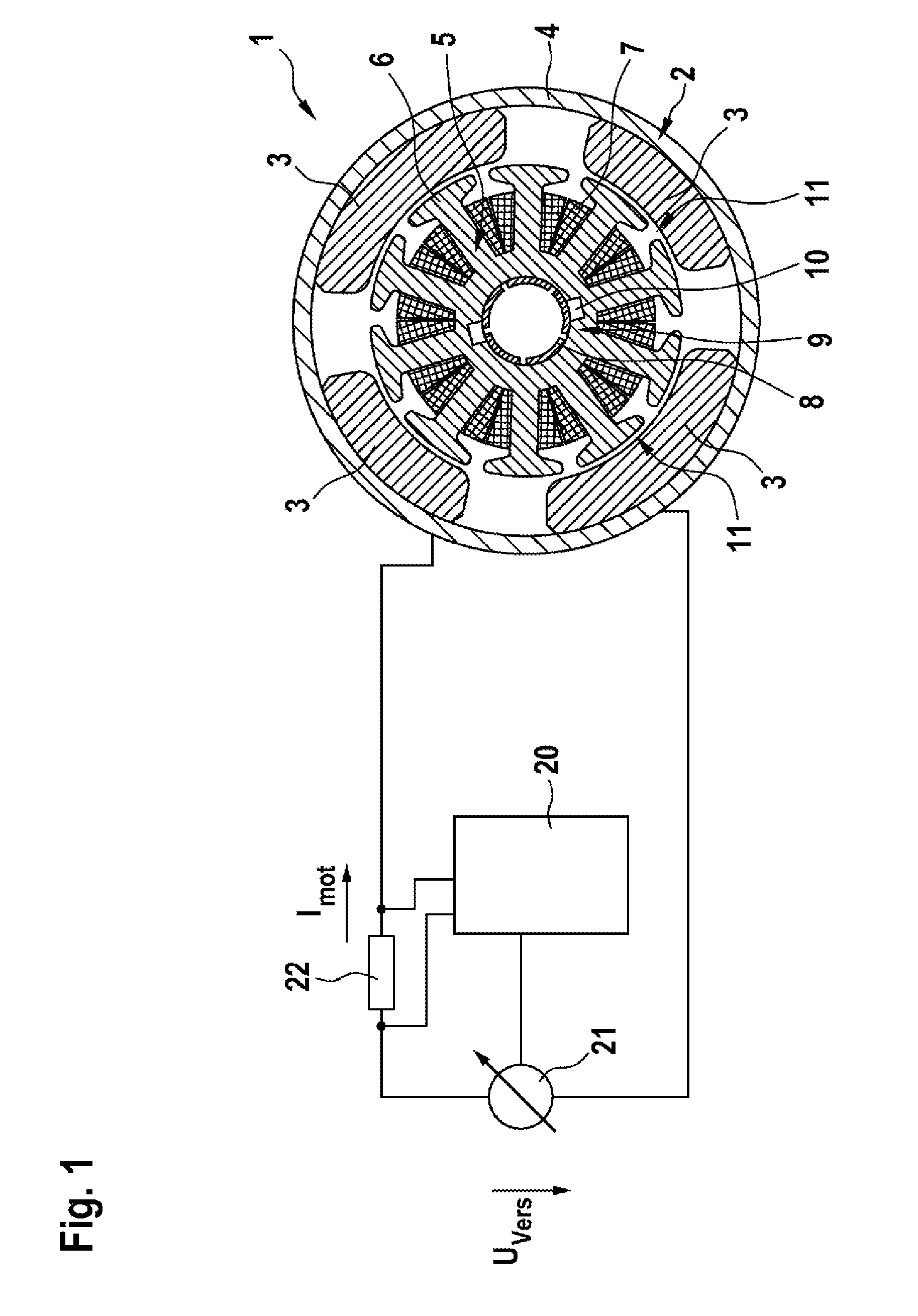
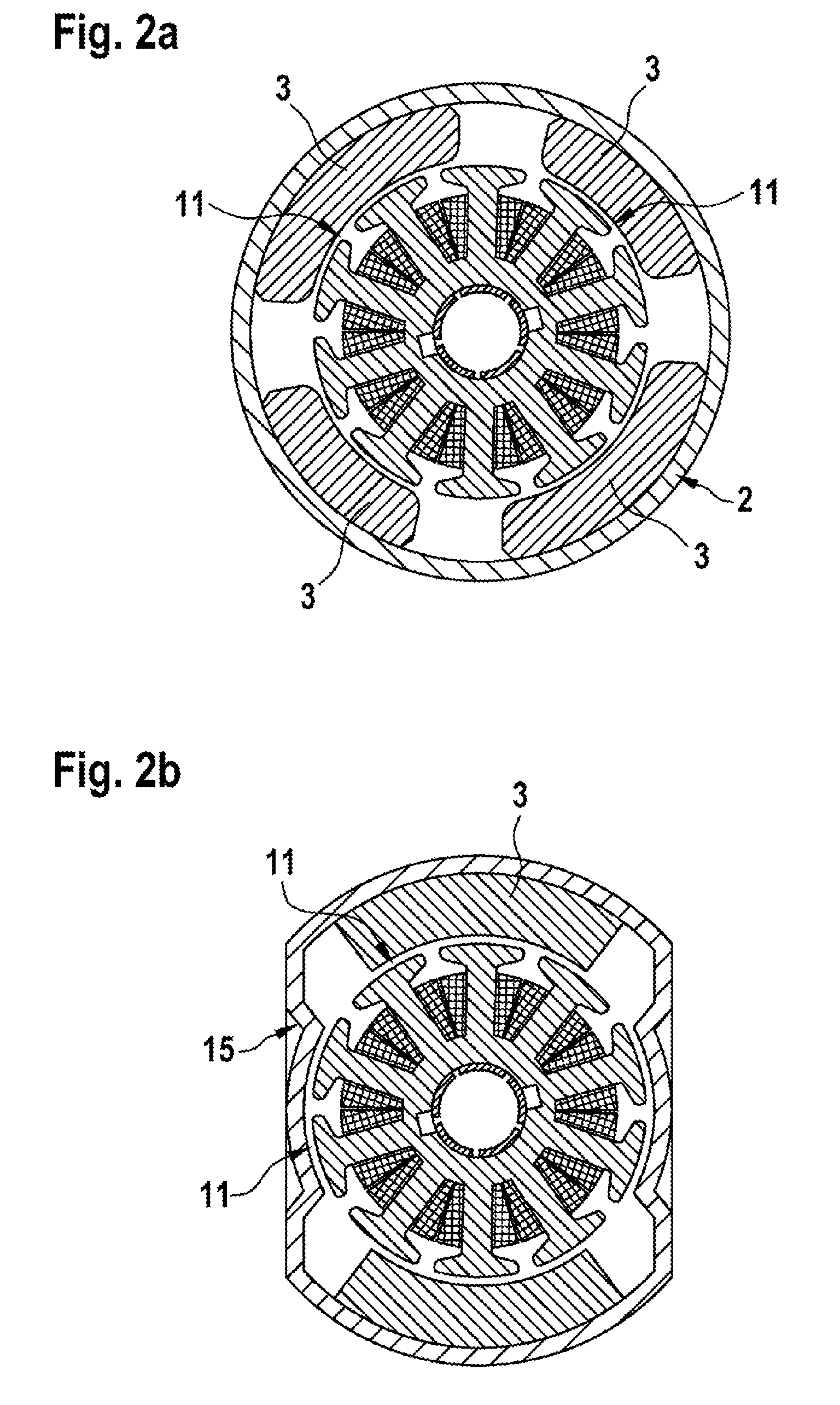
[0023]FIG. 1 shows a schematic illustration of a motor system 1 comprising an electric motor 2 as electrical machine. The electric motor 2 is a brush-commutated DC motor comprising a stator 4, which is provided with one or more permanent magnets 3, and a rotor 5 which is rotatably mounted in an interior of the stator 4.

[0024]The stator 4 is formed with stator poles 11 which produce a stator magnetic field, which is produced by the permanent magnets 3 (stator magnets), in the interior of the stator 4, said stator magnetic field alternating along a circumferential direction. In the present exemplary embodiment, the electric motor 2 is formed with four stator poles 11. Alternative embodiments can also provide more than four stator poles 11, such as six stator poles for example.

[0025]In the illustrated exemplary embodiment, the rotor 5 has ten rotor poles 6 (rotor teeth) which are each surrounded by a rotor coil 7. The rotor coils 7 are each electrically connected to two commutator lami...


PUM


Abstract

The invention relates to a brush-commutated electrical machine (2), comprising: —a rotor (5) with rotor coils (7) which are arranged on rotor poles (6); —a commutator (9) with commutator laminations (8) which are electrically connected to the rotor coils (7), and having two brushes (10) which are arranged offset in relation to one another, with the result that the brushes (10) alternately commutate when the rotor (5) moves; —a stator (4) having stator poles (11) which are arranged in the circumferential direction and at least some of which are provided with stator magnets (3), wherein the stator poles (11) are designed and / or arranged such that an alternating stator magnetic field which is generated by said stator poles in the circumferential direction is formed differently depending on the pole direction of the respective stator pole (11).

Description

BACKGROUND OF THE INVENTION[0001]The present invention relates to brush-commutated electrical machines, in particular measures for ascertaining a rotor position or rotation speed of the electrical machine.[0002]The use of brush-commutated electric motors as actuating motors for DC voltage applications is already known. For example, brush-commutated electric motors are used as drive motors for seat adjusters, window winders, sliding roof systems and the like in a motor vehicle. A common configuration is four- and six-pole DC actuating motors with permanent-magnet excitation comprising a commutator having two brushes.[0003]During operation of electric motors of this kind, current ripple is produced on the supply line owing to the commutation processes. The current ripple corresponds to a periodic signal which is dependent on a rotation speed of the electric motor and of which the fundamental frequency depends on the number of commutator laminations. The current ripple can be used in s...

Claims


Application Information

Patent Timeline
Patent Type & Authority Applications(United States)
IPC IPC(8): H02K23/04H02P7/00
CPCH02P7/0094H02K23/04H02K23/40H02K23/66
Inventor ROOS, GERALD
Owner ROBERT BOSCH GMBH
Why Eureka
Try Eureka