Dental Tool for Customizing Implants, System and Methods Thereof

a technology for customizing implants and dental tools, applied in dental tools, dental surgery, manufacturing tools, etc., can solve the problems of limited directionality control, inability to customize to the patient, and prior art dental implant systems substantially limit clinician's options, so as to improve the maintenance of implants.

Inactive Publication Date: 2015-12-10
ABRACADABRA IMPLANT LTD
View PDF8 Cites 5 Cited by
  • Summary
  • Abstract
  • Description
  • Claims
  • Application Information

AI Technical Summary

Benefits of technology

[0020]Optionally and preferably dedicated tools may be utilized to customize an implant system and/or abutment assembly to form a finish line, which may be individually adjusted in relation with the bone level, soft tissues, abutment's axis, and the occlusal plane. The finish line may be defined and/or positioned with optional dedicated tool. Optionally the finish line may be positioned according to any clinical situation. Most preferably the finish line is configured to be just about parallel with the occlusal plane and/or other finish lines and substantially perpendicular about abutment axis. Most preferably such dedicated tools may provide the achievement of a smooth well positioned finish line with proper width to receive the encountered forces and closely fit with restoration's margins
[0021]Most preferably the tools of the present invention allow an abutment assembly to be adjusted so as to assume a position that is substantially perpendicular to the occlusal plane and just about parallel with adjacent and/or other abutments and/or teeth. Thus essentially, the tools facilitate defining only one path of insertion and retrievability that is substantially parallel to the axis of the abutment and/or

Problems solved by technology

Prior dental implant systems generate major drawbacks by providing unstable connection platforms and limited designs of abutments which restrict the abutment's shape, level of angulation and provide limited directionality control relative to the patient, and therefore cannot be customized to the patient.
Prior art dental implant systems substantially limit clinician's options to properly position an abutment (and the restoration mounted thereon) relative to other abutments and/or teeth of same and/or opposite jaw.
Prior art dental implant systems do not provide an abutment assembly that may be adjusted and/or customized with respect to individual morphology, specific clinical situation of the patient and according the biomechanical principles.
Similarly, current abutments do not allow for, parallel alignment between abutments and/or associated prepared teeth, and/or other teeth involved in the rehabilitation process.
In order to enable rehabilita

Method used


Image

  • Dental Tool for Customizing Implants, System and Methods Thereof
  • Dental Tool for Customizing Implants, System and Methods Thereof
  • Dental Tool for Customizing Implants, System and Methods Thereof

Examples


Embodiment Construction

[0061]The principles and operation of the present invention may be better understood with reference to the drawings and the accompanying description. The following figure reference labels are used throughout the description to refer to similarly functioning components are used throughout the specification herein below.

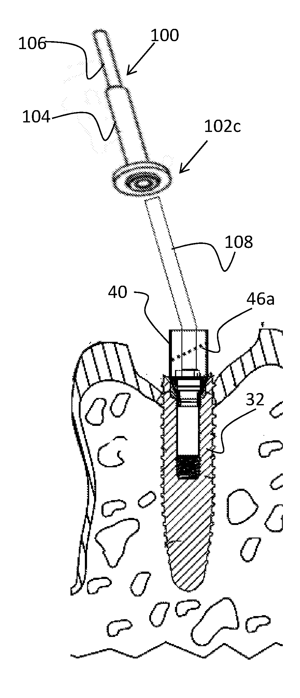
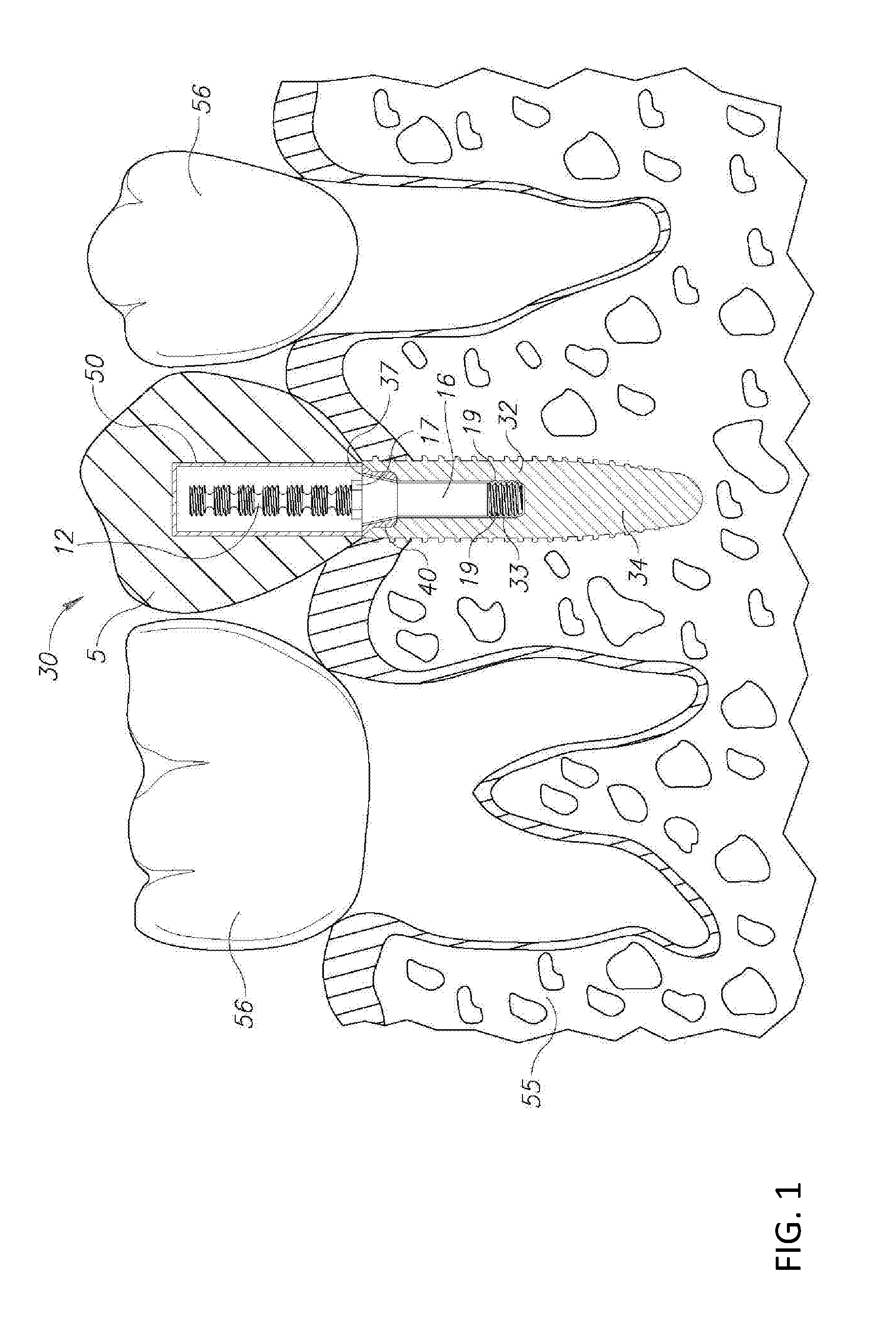
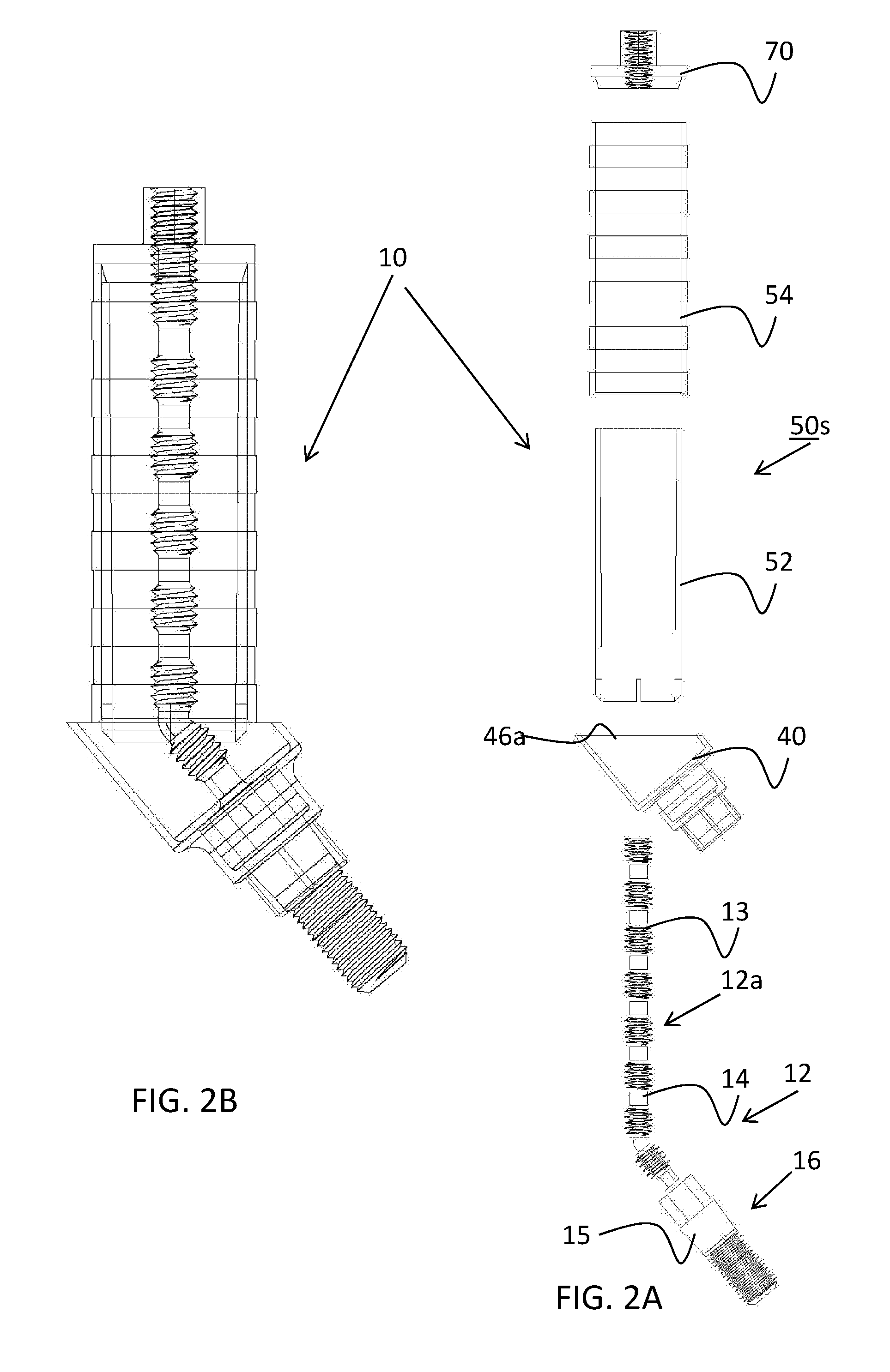
No. #Description 5prosthodontic restoration; 5amounting bore; 10abutment assembly; 11abutment; 12abutment pivot; 12apivot projection; 13engageable portion; 14adjustment portion; 15stabilizing portion; 16pivot mounting member / portion; 17screw head interface; 19screw thread; 30dental implant system; 32conventional implant anchor; 32canchor crestal portion; 33screw thread; 34screw thread; 37opening; 40interface member; 46aflange; 50sleeve; 50csleeve lumen; 54outer sleeve member; 55jawbone; 56residual teeth; 70locking nut;100Cutting Tool;100cTool coupling handle;100hTool conic head;100etooling surface edge;100stooling surface;100wTool Wide head;102head portion;102areceivin...


PUM

PropertyMeasurementUnit
Timeaaaaaaaaaa
Timeaaaaaaaaaa
Volumeaaaaaaaaaa

Abstract

A device, system and method providing a dental tool (100) and a guiding member (108) for customizing at least a portion of a member of a dental implant system by way of milling and/or filing.

Description

FIELD OF THE INVENTION[0001]This disclosed subject matter relates to dental implants in general and in particular to a device for adjusting and / or manipulating portions of dental implant assembly about its various parts.BACKGROUND OF THE INVENTION[0002]In its simplest form dental implant assembly and / or system are known in the art and typically include a dental anchor that is securely inserted into the patient jawbone, replacing the root, a restoration that replaces the tooth crown and an abutment and / or pivot member that interface both the anchor and restoration. Commonly, in the art, the abutment is affixed to the anchor through a fixation screw also known as an abutment screw.[0003]A multitude of prefabricated abutments and implant systems of various designs are offered to clinicians in an effort to provide clinicians with necessary means to successfully restore edentulous patients.[0004]In order to be successful, the implant anchor and all restorative devices associated therewit...

Claims


Application Information

Patent Timeline
IPC IPC(8): A61C8/00A61C13/00
CPCA61C8/0089Y10T409/306552Y10T409/304032A61C13/0006A61C3/02A61C8/005
Inventor HONIG
Owner ABRACADABRA IMPLANT LTD
Why Eureka
Try Eureka