
Micro-bubble generating device

a generation device and micro-bubble technology, applied in water/sewage treatment by oxidation, carburetating air, separation processes, etc., can solve the problems of high cost, high cost of filter replacement, and large amount of wastewater polluting the environment, so as to improve detergence ability and water saving efficiency. , the effect of double speed

Active Publication Date: 2015-12-10
LAI CHING HO
View PDF0 Cites 14 Cited by
  • Summary
  • Abstract
  • Description
  • Claims
  • Application Information

AI Technical Summary

Benefits of technology

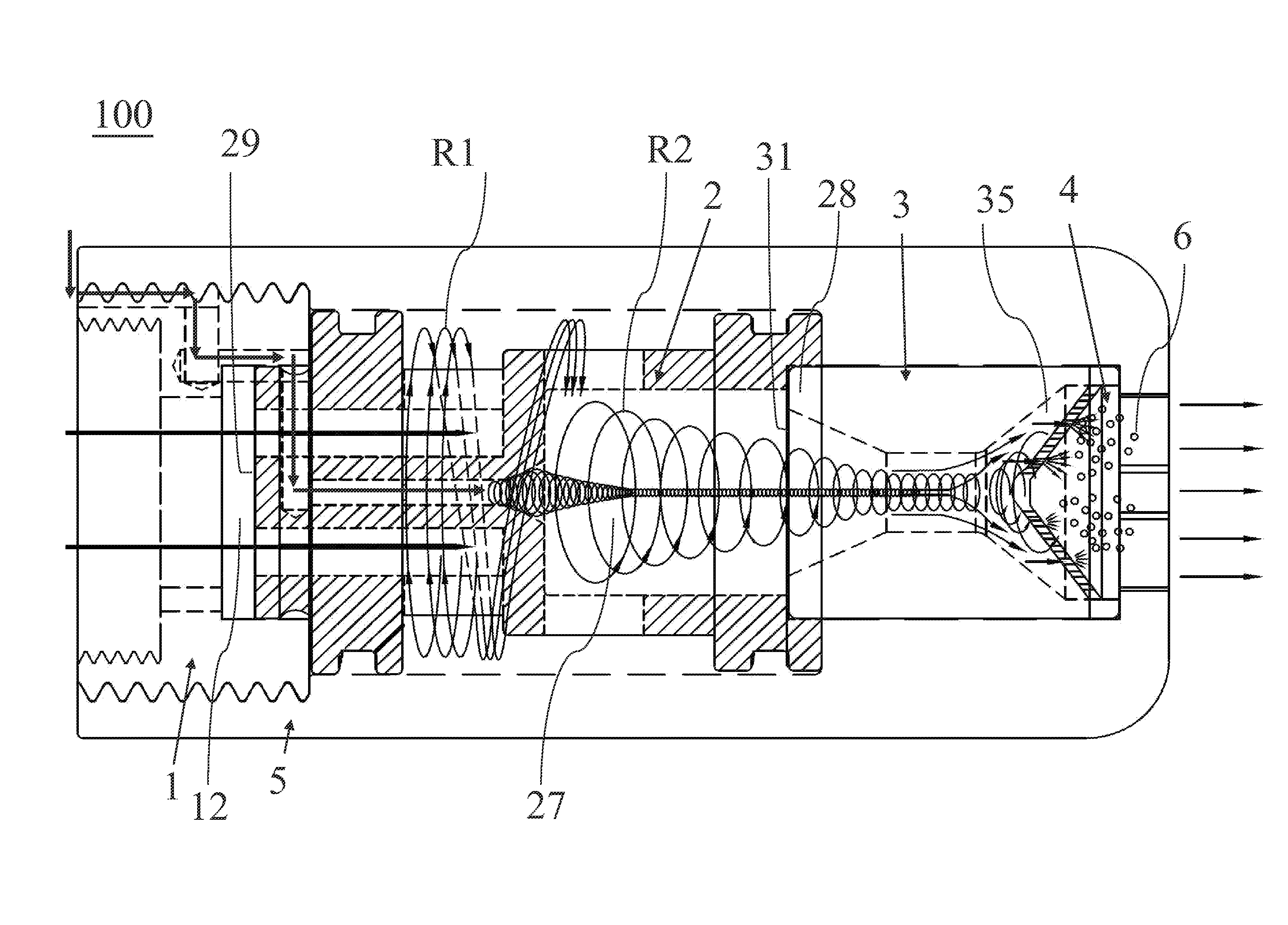
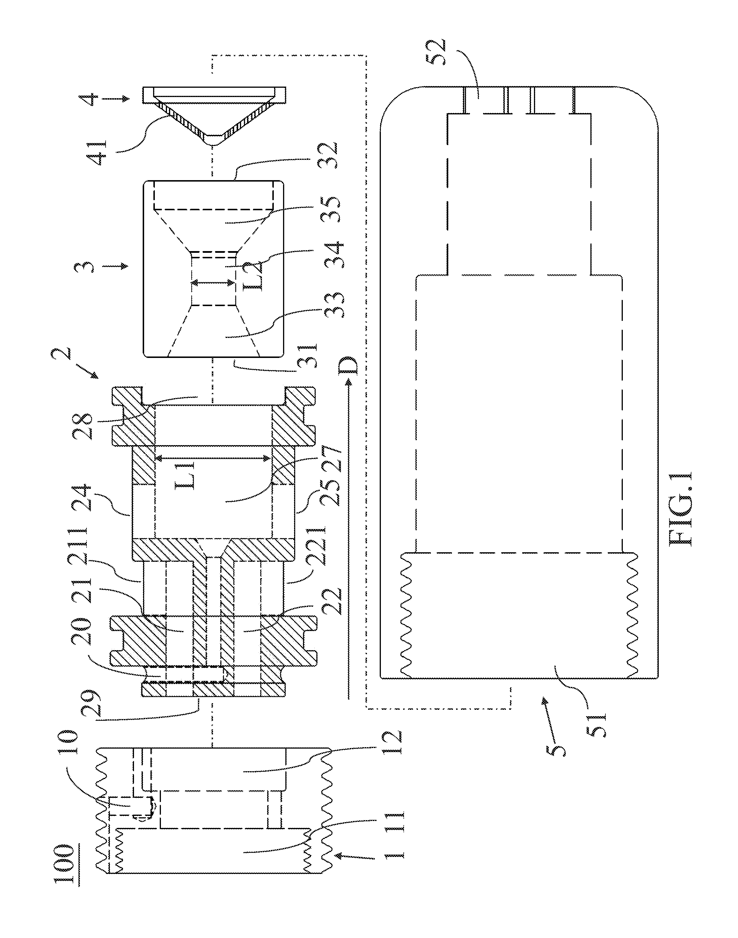
The present invention is a micro-bubble generating device that can be used in various industries and applications such as shower or kitchen faucet, or outlet in washing machine. The device can purify water, improve skin appearance, sterilize, save water and lower demand for chemical cleaning agents. The device can be easily installed and the size thereof is small. The device includes an accelerating tube to generate micro-bubbles which can stay in water for a long time and the diameter of the micron bubble is small enough to include better detergence ability. The micro-bubbles generated by the device can have various cleaning effects.

Problems solved by technology

The idea of purifying water by people is to install a water purifier to clean water or implement silver material for sterilizing, and the cost thereof is high and it is required to change filter frequently.
Therefore it would generate a lot of wastewater to pollute environment.
Generally, the quantity of the filtered water is not enough to supply agriculture, fishery and the like, and it only can be used for drinking water.
The gas dissolving type is to inject high pressure gases into the liquid and the disadvantage thereof is to require consume a greater amount of gases.
The cost of the gas dissolving type is high and it is not convenient to implement in any different industries or home use.
It is not convenient to be used for home, medium and small size agriculture and fishery.
In addition, since the quantity of bubbles is not enough and the time for the bubble staying in water is short, it is not good enough to purify water or sterilize.

Method used


Image

  • Micro-bubble generating device
  • Micro-bubble generating device
  • Micro-bubble generating device

Examples


Embodiment Construction

[0014]In the following detailed description of the preferred embodiments, reference is made to the accompanying drawings which form a part hereof, and as shown by way of illustration specific embodiments in which the invention may be practiced. In this regard, directional terminology, such as “top,”“bottom,”“front,”“back,”“left,”“right,”“inside,”“outside,”“side,” etc., is used with reference to the orientation of the FIG.(s) being described. As such, the directional terminology is used for purposes of illustration and is in no way limiting the present invention.

[0015]The micron bubbles generated by the micro-bubble generating device in the present invention are very tiny bubble in micrometers and that is why it is called the micron bubble. The micron bubbles are made by water and air and the particle size thereof is 10 micrometer or less. The micron bubbles include very strong detergency. When the micron bubbles are generated, the contact surface area between the water and air is in...


PUM

PropertyMeasurementUnit
diameteraaaaaaaaaa
particle sizeaaaaaaaaaa
sizeaaaaaaaaaa

Abstract

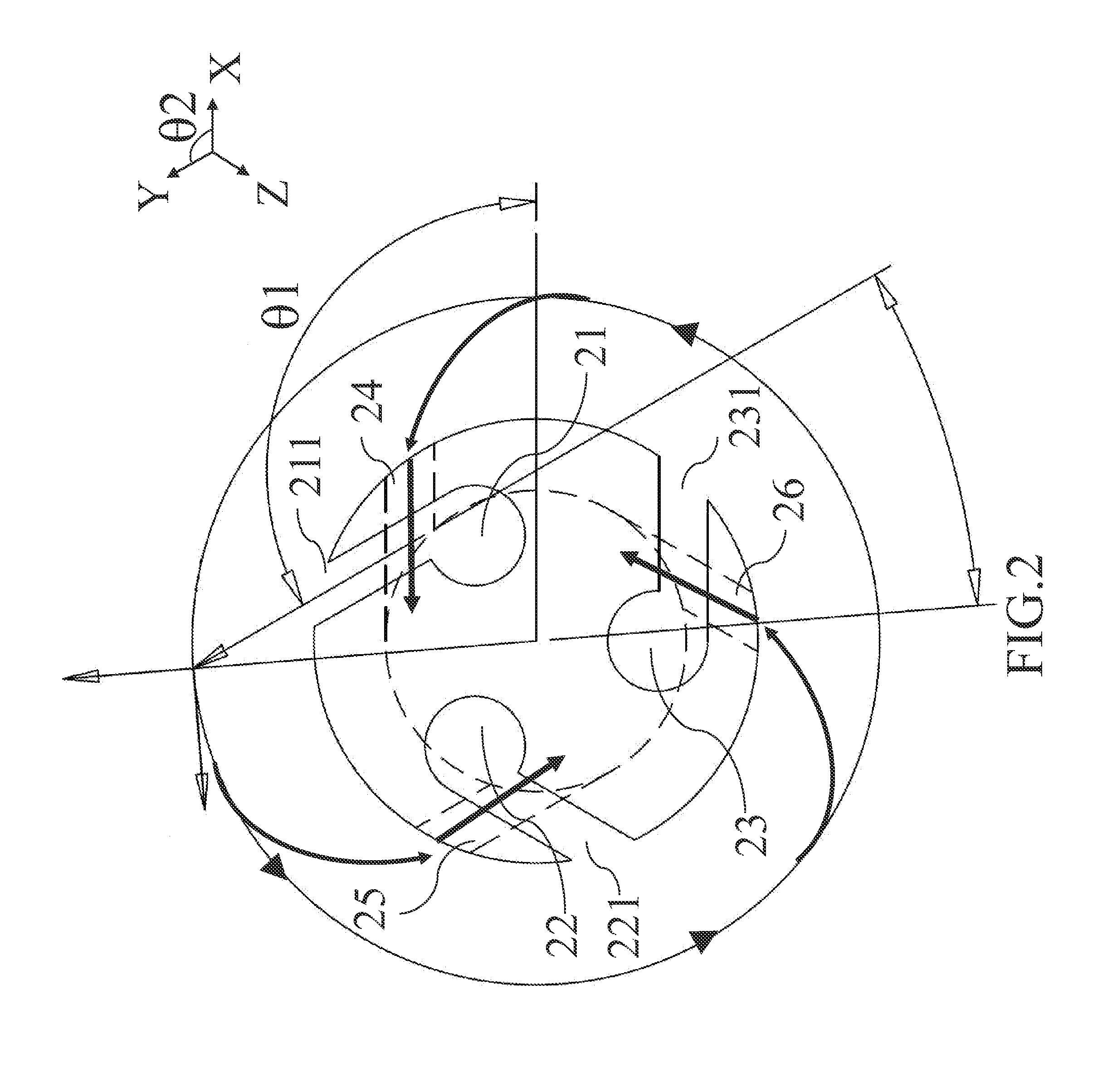
A micro-bubble generating device is provided in the present invention and a shell covers the adapter coupling head, the accelerating tube, the venture tube and the conical net to be the micro-bubble generating device. When the water flows from the adapter coupling head to the accelerating pipe, the water will double the speed by the first water flow rotation and the second water flow rotation and guide the external ambient air via the first air flow channel and the second air flow channel into the inner tube of the accelerating tube. And then, the water will flow through the venture tube to generate a high rotation speed and high dynamic pressure water to make the air burst. Therefore, water will produce a plurality of small bubbles. After the water flows through the cutting holes, the small bubbles are further cut to form a plurality of micron bubbles.

Description

FIELD OF THE INVENTION[0001]The present invention relates to a field of micro-bubble generating device, and more particularly relates to a micro-bubble generating device for purifying water.BACKGROUND OF THE INVENTION[0002]The idea of purifying water by people is to install a water purifier to clean water or implement silver material for sterilizing, and the cost thereof is high and it is required to change filter frequently. Therefore it would generate a lot of wastewater to pollute environment. Generally, the quantity of the filtered water is not enough to supply agriculture, fishery and the like, and it only can be used for drinking water.[0003]The conventional micro-bubble generating device can be divided into a gas dissolving type and a hydrodynamic type. The gas dissolving type is to inject high pressure gases into the liquid and the disadvantage thereof is to require consume a greater amount of gases. The cost of the gas dissolving type is high and it is not convenient to imp...

Claims


Application Information

Patent Timeline
Patent Type & Authority Applications(United States)
IPC IPC(8): B01F3/04C02F1/72
CPCB01F3/04106C02F2303/04B01F2215/0052C02F1/72B01F23/23B01F23/2373B01F2025/913B01F25/3121B01F25/45231B01F23/231B01F2101/305
Inventor LAI, CHING-HO
Owner LAI CHING HO
Learn More