Turbocharger impeller, method of manufacturing the same, turbocharger, and turbocharger unit

a technology of impeller and turbocharger, which is applied in the direction of machines/engines, liquid fuel engines, forging/pressing/hammering apparatus, etc., can solve the problems of increasing turbulence, affecting the quality of the product, and requiring a relatively long operation and/or production cycle time to complete precision investment castings, etc., to achieve the effect of suppressing pressure loss

Active Publication Date: 2015-12-10
TOYOTA IND CORP +1
View PDF11 Cites 21 Cited by
  • Summary
  • Abstract
  • Description
  • Claims
  • Application Information

AI Technical Summary

Benefits of technology

[0022]As an alternative to the configuration described above, the fluid swirl-regulating portion may extend in the radial direction across a center of a cross-section of the inlet elbow to bridge between portions of the inner surface of the discharge port of the inlet elbow. Further, the fluid swirl-regulating portion may have a plate extending in the longitudinal direction of the inlet elbow. Also, the fluid swirl-regulating portion may be integral with the inner surface of the inlet elbow, or may be formed as a member separate from the inner surface that may connect to the inner surface of the inlet elbow as needed. Thus, the fluid swirl-regulating portion may suppress, for example, excessive and / or undesirable, the pressure loss of the fluid transferred (force-fed). Thus, the fluid-swirl-regulating portion may work in conjunction with grooves formed in the impeller to suppress pressure loss.

Problems solved by technology

However, precision investment casting often requires a relatively long operation and / or production cycle time to complete, relative to other forms of casting, for example.
Machining, however, may create various undesirable grooves due to the machining on the surfaces of the vane portions and / or the hub portion.
Such a groove may create and / or increase turbulence experienced by a fluid flowing across an impeller.
As a result, an impeller made by machining may actually diminish engine intake efficiency due to turbulence caused by grooves and / or other imperfections in the impeller, in comparison an impeller formed by precision investment casting.
However, such surface processing may require an even longer period of time to complete, compared with the conventional precision investment casting, thus the method may not desirable for efficient high-volume impeller production.
Thus, these grooves may not be formed to suppress pressure loss at an inlet portion.
Thus, these methods do not help to produce the impeller in a shorter time.

Method used


Image

  • Turbocharger impeller, method of manufacturing the same, turbocharger, and turbocharger unit
  • Turbocharger impeller, method of manufacturing the same, turbocharger, and turbocharger unit
  • Turbocharger impeller, method of manufacturing the same, turbocharger, and turbocharger unit

Examples


Embodiment Construction

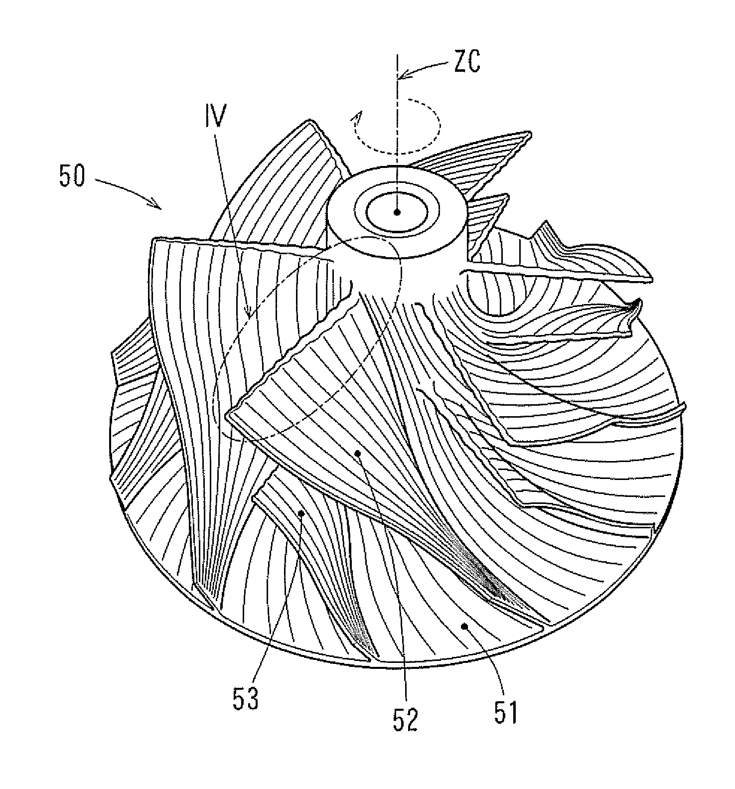
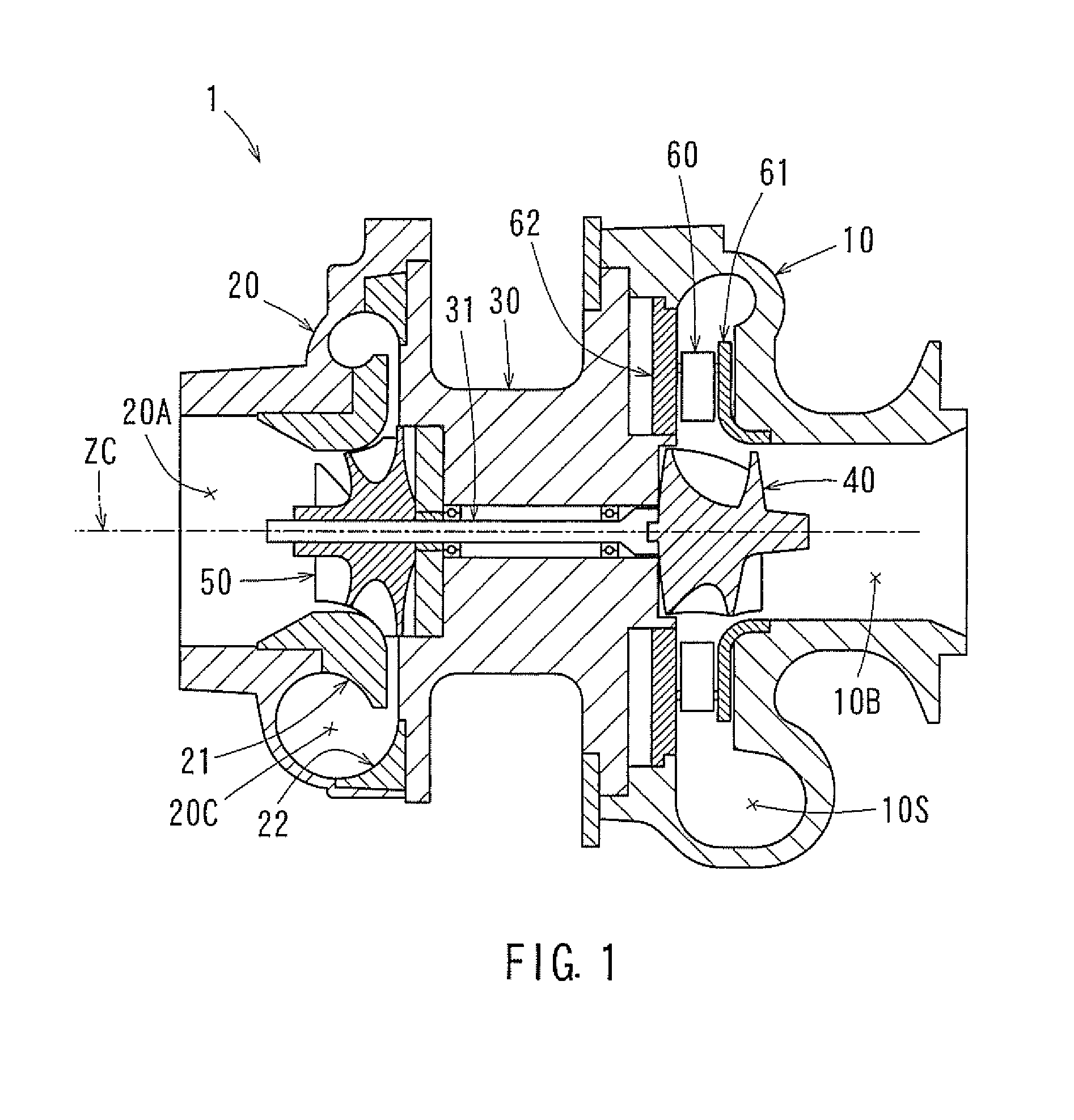
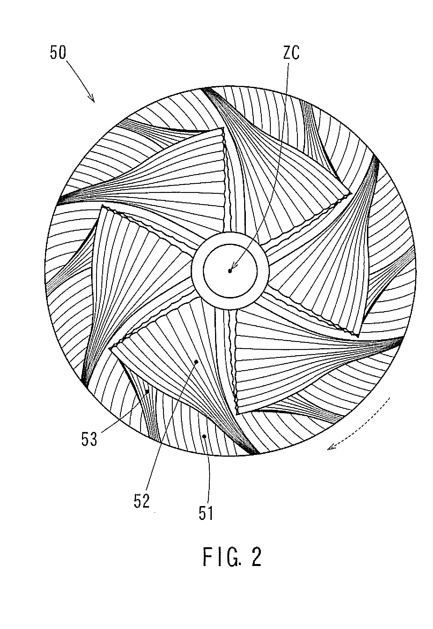
[0035]A turbocharger 1 will be described with reference to FIG. 1. The turbocharger 1 may be configured to attach to and / or coupled with an internal combustion engine mounted, for example, in a vehicle such as an automobile. The turbocharger 1 has three housings: an exhaust housing 10, an intake housing 20 and a bearing housing 30. Bearings (not shown in the FIGS.) support a shaft 31 to allow the shaft 31 to rotate freely about a rotation axis (herein referred to as “ZC” in at least FIG. 1) within the bearing housing 30. A turbine 40 is provided inside the exhaust housing 10. Also, an impeller 50 (i.e. a turbocharger impeller) is provided inside the intake housing 20.

[0036]The shaft 31 has a first end in the exhaust housing 10, and a second end, opposing the first end, in the intake housing 20. The turbine 40 may be attached to and / or connected with on the first end. The impeller 50 may be attached to and / or connected with on the second end. Turbine 40 and the impeller 50 are connec...


PUM

PropertyMeasurementUnit
height H2aaaaaaaaaa
height H1aaaaaaaaaa
diameteraaaaaaaaaa

Abstract

A turbocharger impeller is provided with a hub portion with a plurality of vane portions extending outwardly thereof. The hub portion is substantially shaped as a truncated cone with a diameter that gradually increases along a rotation axis. The vane portions are formed on a surface of the hub portion and guide a fluid flowing along the rotation axis radially outward relative to the hub portion. Grooves are formed in and/or on surfaces of the vane portions along a direction of the fluid flowing radially outward during rotation of the impeller. Protruding crest portions are formed between adjacent grooves. Crest portions in a central region near the rotation axis are lower in height than crest portions in an outer region further away from the rotation axis.

Description

CROSS-REFERENCE TO RELATED APPLICATIONS[0001]The present application is a National Phase entry of, and claims priority to, PCT Application No. PCT / JP2014 / 051243, filed Jan. 22, 2014, which claims priority to Japanese Patent Application No. 2013-009996, filed Jan. 23, 2013, both of which are incorporated herein in their entireties by reference.BACKGROUND[0002]The present invention relates to a turbocharger impeller, a method of manufacturing the same, a turbocharger, and a turbocharger unit.[0003]A turbocharger is used, for example, for an internal combustion engine mounted in a vehicle. The turbocharger recovers energy of an exhaust gas of the internal combustion engine through a turbine. The recovered energy rotates an impeller (compressor) connected to the turbine via a shaft. The impeller rotates, and the internal combustion engine is supercharged with intake air. As a result, the intake efficiency is enhanced, and the internal combustion engine is improved in terms of output and...

Claims


Application Information

Patent Timeline
Patent Type & Authority Applications(United States)
IPC IPC(8): F01D5/02B23P15/00F02B39/00
CPCF01D5/02Y10T29/49323B23P15/00F02B39/00F04D29/30F04D25/024F04D29/284F04D29/681F02B37/24B23C3/18F05D2220/40
Inventor MATSUDA, MASAAKITANEDA, YOSHIOHIROTA, SHUICHIHARIMA, HIDETOSHIINOUE, NOBUHIKOYONEZAWA, KOICHITSUKIYAMA, TAKASHI
Owner TOYOTA IND CORP
Why Eureka
Try Eureka