Check patentability & draft patents in minutes with Patsnap Eureka AI!

Propellant feed circuit and a cooling method

a technology of propellant feed circuit and cooling method, which is applied in the field of aerospace, can solve the problems of difficult to remove the heat generated by such devices and few channels

Inactive Publication Date: 2015-12-10
ARIANEGRP SAS
View PDF11 Cites 0 Cited by
  • Summary
  • Abstract
  • Description
  • Claims
  • Application Information

AI Technical Summary

Benefits of technology

This solution enables precise temperature regulation of heat sources, increased heat absorption capacity, and effective cooling using cryogenic propellants like liquid hydrogen, while also maintaining internal tank pressure and preventing cavitation in pumps.

Problems solved by technology

However, constraints specific to this field can make it very difficult to remove the heat generated by such devices.
In particular in the vacuum of space, there are very few channels for removing heat.

Method used


Image

  • Propellant feed circuit and a cooling method
  • Propellant feed circuit and a cooling method
  • Propellant feed circuit and a cooling method

Examples


Embodiment Construction

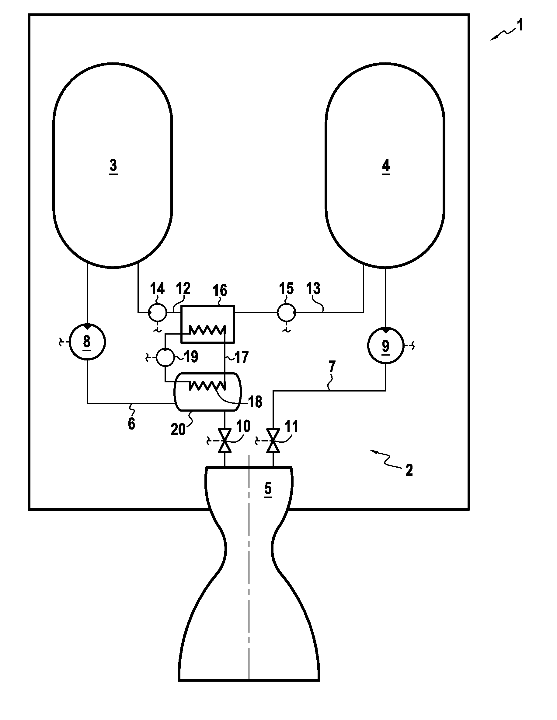
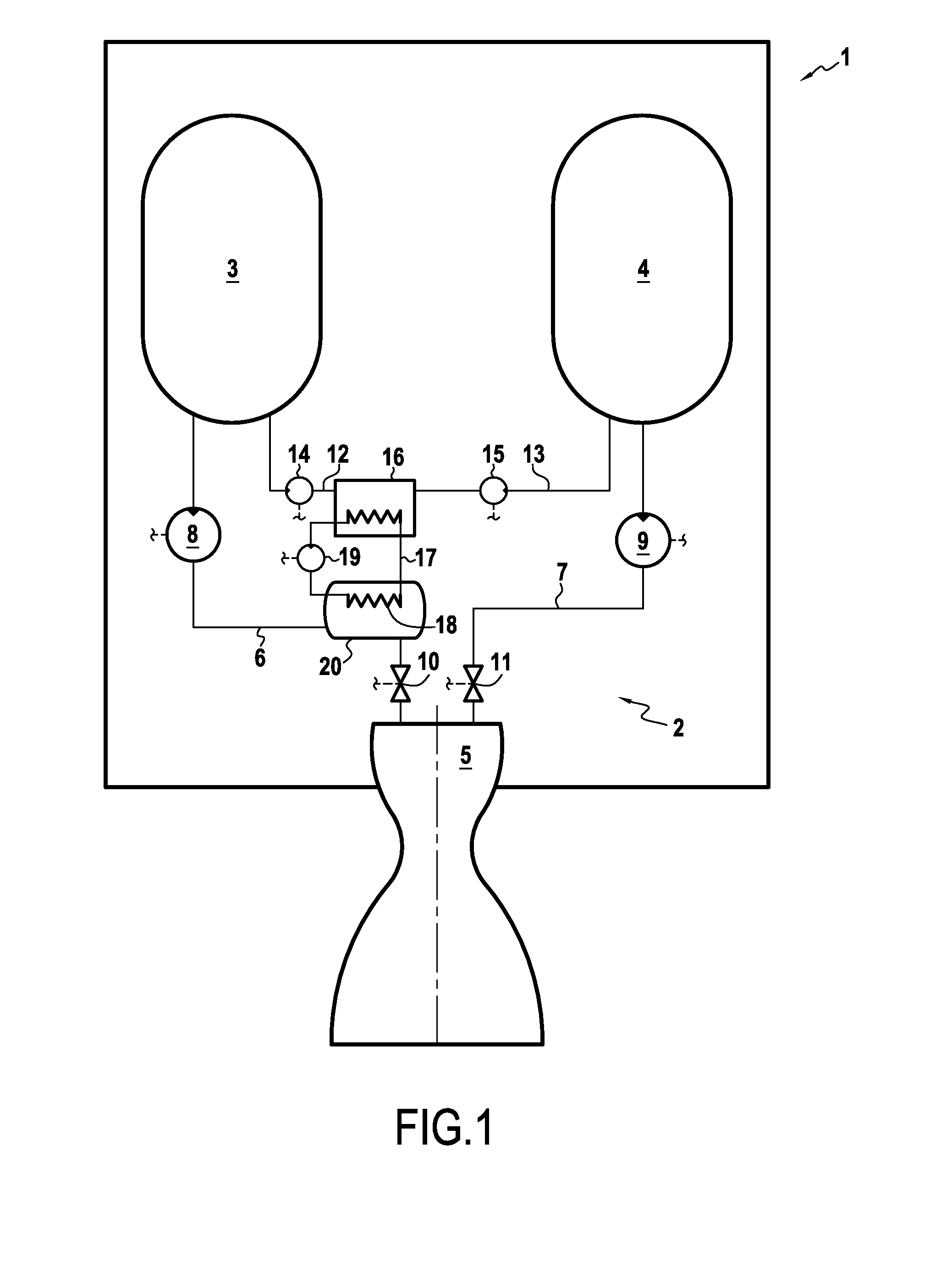
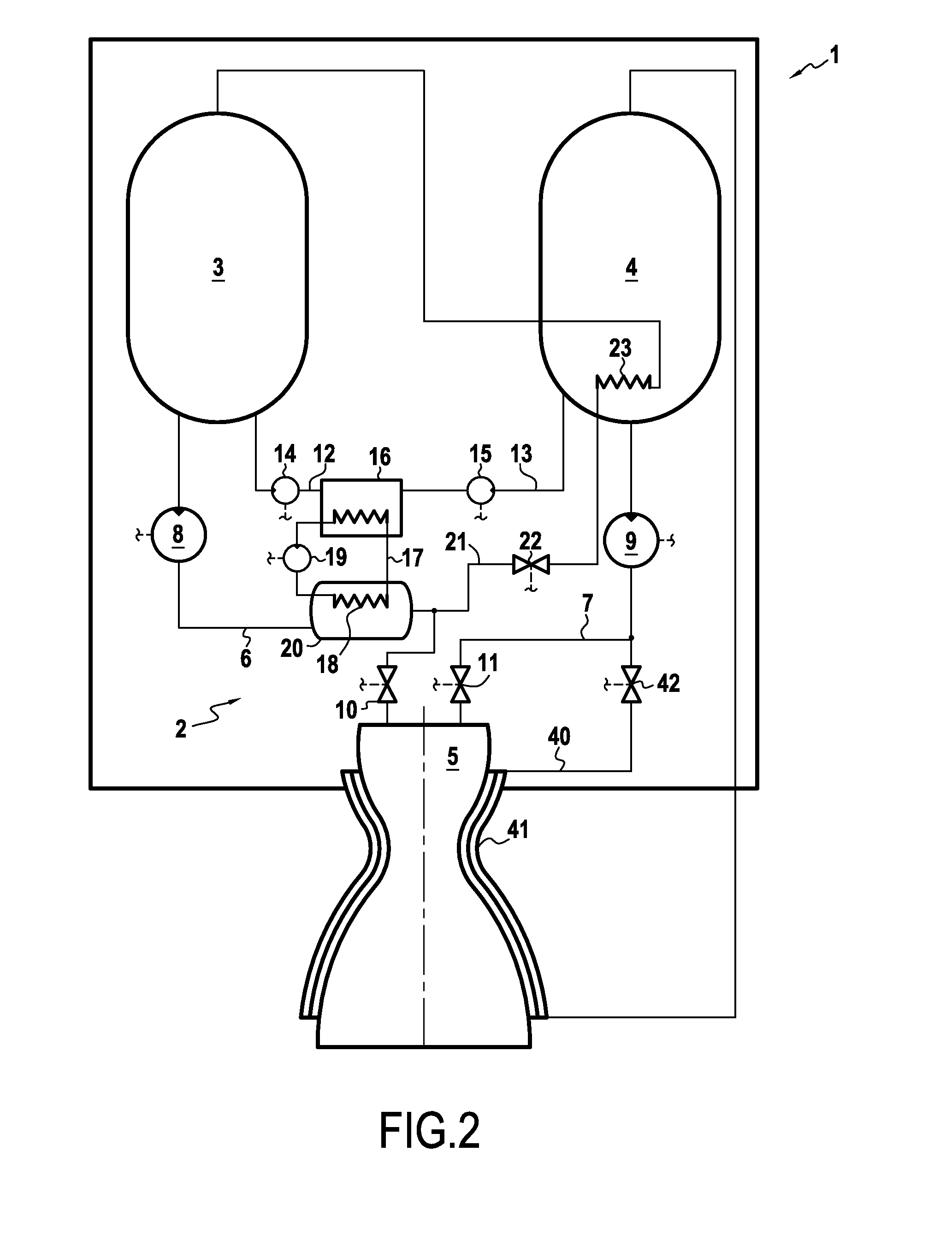
[0018]FIG. 1 is a diagram showing a vehicle 1, which may for example be a stage of a space launcher. For its propulsion, this vehicle 1 has a liquid propellant rocket-engine 2 with a first tank 3 for a first propellant, a second tank 4 for a second propellant, a thrust chamber 5 for combustion of a mixture of the two propellants and for accelerating the gas that results from combustion of the mixture, a first feed circuit 6 connected to the first tank 3 and to the first chamber 5 in order to bring the first propellant from the first tank 3 to the thrust chamber 5, and a second feed circuit 7 connected to the second tank 4 and to the thrust chamber 5 in order to bring the second propellant from the second tank 4 to the thrust chamber 5. The first and second propellants may be cryogenic propellants such as liquid hydrogen and liquid oxygen. Each of the feed circuits 6, 7 comprises a pump 8, 9 for causing the respective propellant to flow through each feed circuit 6, 7, and outlet valv...


PUM


Abstract

The invention relates to the aerospace field, and in particular to the field of vehicles propelled by rocket engines. In particular, the invention relates to a feed circuit (6) for feeding a rocket engine (2) at least with a first liquid propellant, the feed circuit including at least one buffer-tank (20) for said first liquid propellant and a first heat exchanger (18) that is incorporated in said buffer tank (20) and suitable for being connected to a cooling circuit (17) for cooling at least one heat source in order to cool said heat source by transferring heat to the first propellant.

Description

BACKGROUND OF THE INVENTION[0001]The present invention relates to the aerospace field, and in particular to the field of vehicles propelled by rocket engines.[0002]In the description below, the terms “upstream” and “downstream” are defined relative to the normal flow direction of propellants in the feed circuits of a rocket engine.[0003]One of the main concerns in this field is that of obtaining satisfactory cooling of on-board heat sources. Specifically, in order to ensure that they operate properly, certain heat-generating devices, e.g. such as fuel cells, and batteries or electronic circuits, may need to have their operating temperatures maintained within a relatively narrow temperature range. However, constraints specific to this field can make it very difficult to remove the heat generated by such devices. In particular in the vacuum of space, there are very few channels for removing heat.OBJECT AND SUMMARY OF THE INVENTION[0004]The present invention seeks to remedy those drawb...

Claims


Application Information

Patent Timeline
Patent Type & Authority Applications(United States)
IPC IPC(8): F02K9/60
CPCF02K9/605F02K9/60F02K9/46F05D2260/20F05D2260/205F02K9/44F02K9/64F02K9/40F02K9/972
Inventor VUILLAMY, DIDIERROZ, GERARD
Owner ARIANEGRP SAS
Features
  • R&D
  • Intellectual Property
  • Life Sciences
  • Materials
  • Tech Scout
  • Unparalleled Data Quality
  • Higher Quality Content
  • 60% Fewer Hallucinations
Learn More