Charging facility information providing system and electrically driven vehicle

a charging facility and information technology, applied in the direction of navigation instruments, instruments, transportation and packaging, etc., can solve problems such as the application of load to the user

Active Publication Date: 2015-12-10
MITSUBISHI ELECTRIC CORP
View PDF5 Cites 17 Cited by
  • Summary
  • Abstract
  • Description
  • Claims
  • Application Information

AI Technical Summary

Benefits of technology

[0007]It is an object of the present invention to provide a charging facility information providing system capable of acquiring optimum charging plan and charging facility information without applying the load to the user.

Problems solved by technology

In such a case, in addition to searching for a route to a destination by a navigation system or the like, it is necessary for such a user to search charging facilities on peripheries of the route in advance, and this is cumbersome.
However, in the method of Japanese Patent Application Laid-Open No. 2013-250801, there has been a problem in that, in addition to an already placed charging system, the mobile communication terminal is required to acquire information of the charging facilities, and the current place information, the destination information and the residual quantity of the power source must be transmitted to the server using the mobile communication terminal, resulting in application of a load to the user.

Method used


Image

  • Charging facility information providing system and electrically driven vehicle
  • Charging facility information providing system and electrically driven vehicle
  • Charging facility information providing system and electrically driven vehicle

Examples


embodiment

Preferred Embodiment

[0031]

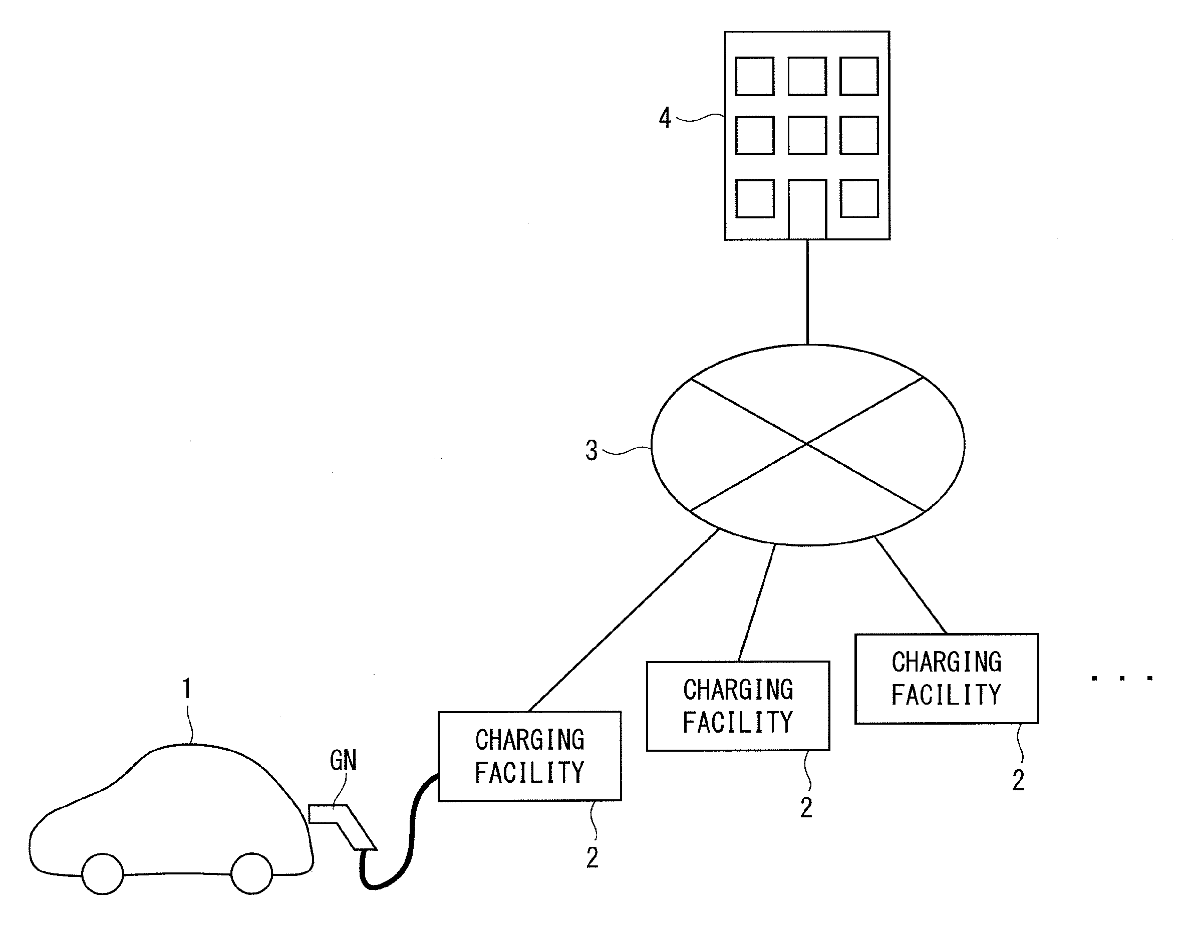
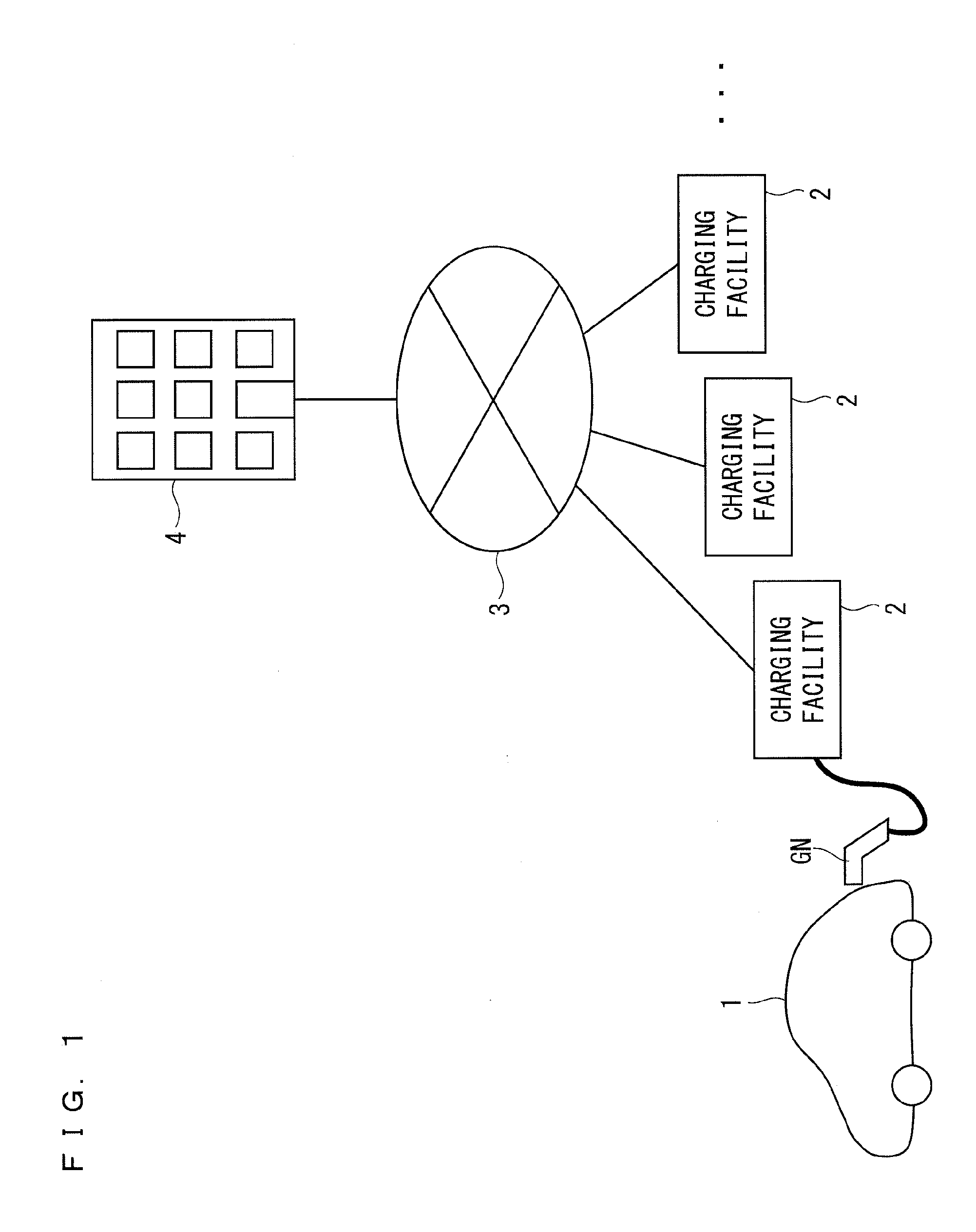
[0032]FIG. 1 is a schematic diagram illustrating a configuration of a charging facility information providing system according to a preferred embodiment of the present invention. As illustrated in FIG. 1, the charging facility information providing system is composed of: an electrically driven vehicle 1; a plurality of charging facilities 2 provided on parking spaces such as houses and shops; an information network 3; and a management center 4 that manages power supply from the charging facilities 2 to the electrically driven vehicle 1.

[0033]The electrically driven vehicle 1 is, for example, such as an electric vehicle (EV) and a plug-in hybrid electric vehicle (PHEV), which is capable of running by using, as a drive source, a motor driven by power accumulated in a storage battery. In a case where the electrically driven vehicle 1 is the EV, the electrically driven vehicle 1 runs by using a motor (not shown) as a drive source. In a case where the electrical...


PUM


Abstract

A charging facility information providing system includes: an electrically driven vehicle, a charging facility, and a management center, wherein, in the case of charging the storage battery, the electrically driven vehicle and the charging facility perform charge communication, the electrically driven vehicle sends travel plan information, to the charging facility by the charge communication during the charge of the storage battery, the charging facility transfers the travel plan information sent from the electrically driven vehicle to the management center through an information network, then based on the travel plan information received from the charging facility, the management center creates a charging plan which is matched with the running route of the electrically driven vehicle, acquires charging facility information of a charging facility at a scheduled charging place included in the charging plan, and sends the charging plan and the charging facility information to the charging facility through the information network and the charging facility transfers the acquired charging plan and the charging facility information to the electrically driven vehicle by the charge communication.

Description

BACKGROUND OF THE INVENTION[0001]1. Field of the Invention[0002]The present invention relates to a charging facility information providing system, and particularly, relates to a charging facility information providing system for an electrically driven vehicle such as an EV (electric vehicle) and a PHEV (plug-in hybrid electric vehicle).[0003]2. Description of the Background Art[0004]In a long-distance movement by an electrically driven vehicle at leisure or the like, a situation is considered where a driver does not know via which charging facility the driver should pass since the driver drives on an unfamiliar area. In such a case, in addition to searching for a route to a destination by a navigation system or the like, it is necessary for such a user to search charging facilities on peripheries of the route in advance, and this is cumbersome.[0005]As a charging facility information providing system for an electrically driven vehicle, for example, as disclosed in Japanese Patent Ap...

Claims


Application Information

Patent Timeline
Patent Type & Authority Applications(United States)
IPC IPC(8): G01C21/34B60L11/18G01C21/36
CPCG01C21/3407B60L11/1824G01C21/3605G01C21/3469B60L2240/60B60L2240/72B60L2250/14B60L53/62B60L53/66G01C21/3679G06Q10/06Y02T10/70Y02T10/7072Y02T10/72Y02T90/12Y02T90/16Y02T90/14
Inventor TAKEHARA, TAKAYOSHIMATSUNAGA, TAKANORISATAKE, TOSHIHIDE
Owner MITSUBISHI ELECTRIC CORP
Why Eureka
Try Eureka