Method and apparatus of simultaneous spatial light modulator beam steering and system aberration correction

a technology of beam steering and beam beam, which is applied in the field of simultaneous spatial light modulator beam steering and system aberration correction, can solve the problems of significant weight and size restrictions on the device, the laser power in the desired direction is typically not optimized, and the slm cannot be adaptively phase corrected, so as to facilitate the use of lower-cost, lower-quality optics, and eliminate the tolerable lens aberration and other problems. , the effect of simplifying the design and operation

Active Publication Date: 2015-12-17
THE UNITED STATES OF AMERICA AS REPRESENTED BY THE SECRETARY OF THE NAVY
View PDF9 Cites 0 Cited by
  • Summary
  • Abstract
  • Description
  • Claims
  • Application Information

AI Technical Summary

Benefits of technology

[0010]Optionally, an embodiment of the invention provides non-mechanical holographic beam steering in an optical system that not only steers the beam in the appropriate direction, but also corrects for field-dependent, system optical lens aberrations simultaneously. Optionally, an embodiment of the invention removes lens tolerancing, lens aberrations, size and weight restrictions by actively correcting for lens aberrations while simultaneously using the SLM as a steering device, eliminating the need for a separate steering mirror. Such embodiments of the invention facilitate use of lower-cost, lower-quality optics while still maintaining a diffraction-limited beam in a wide-angle steering system.
[0011]Advantageously, a benefit of an embodiment of the invention is the simplicity in its design and operation. Beam steering is accomplished solely with a spatial light modulator and a wide-field optical system, which could be as simple as a single lens. No additional mechanical devices and / or mirrors are necessary to accomplish beam steering in at least one embodiment of the invention. In addition to the SLM acting as a steering device, the SLM also simultaneously acts as a wavefront corrector, reducing the requirement on high-precision, costly optics that minimize aberrations in low f-number optical systems. Whereas high-precision optical systems require multiple lenses to correct for the optical aberrations; this device reduces that requirement, allowing for a smaller, lighter system.

Problems solved by technology

The method of redirecting and steering optical beams, which utilizes a fast steering mirror, imposes significant weight and size restrictions on the device.
No adaptive phase correction is performed with the SLM to correct for aberrations that may be present due to the optical elements in the system.
Therefore, the laser power in the desired direction is typically not optimized because wide-field of view optics generally cause optical aberrations.
Since a lens is used to angularly amplify the transmitted lower order beam, the lens increased field of regard will typically have optical aberrations yet there is no apparent plan to compensate for them in this design.
Methods that utilize the spatial light modulator as a steering device, but which do not correct for system aberrations impose tight tolerance and lens design requirements on the system's optical elements in order to maintain a tight, focused beam.

Method used


Image

  • Method and apparatus of simultaneous spatial light modulator beam steering and system aberration correction
  • Method and apparatus of simultaneous spatial light modulator beam steering and system aberration correction
  • Method and apparatus of simultaneous spatial light modulator beam steering and system aberration correction

Examples


Embodiment Construction

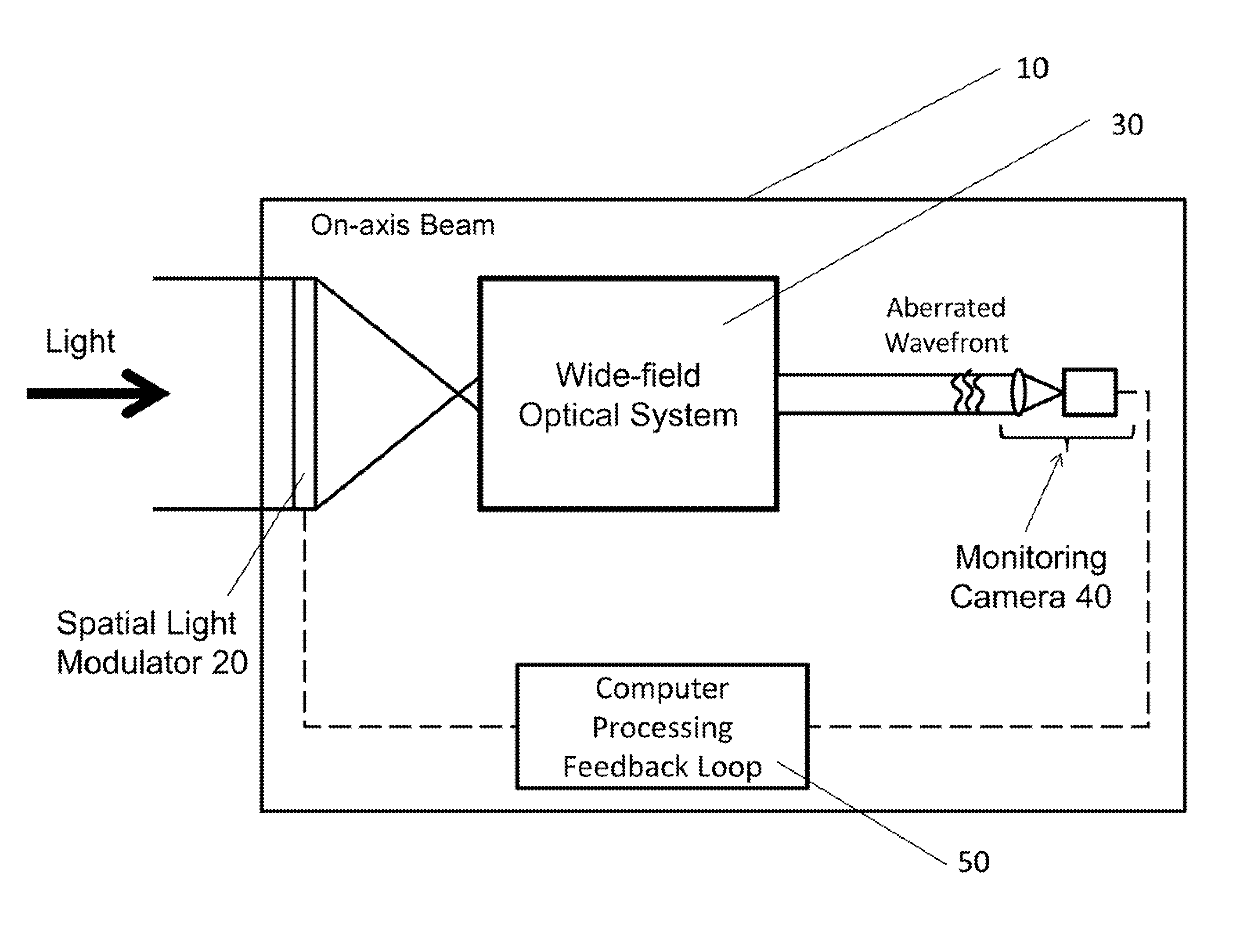
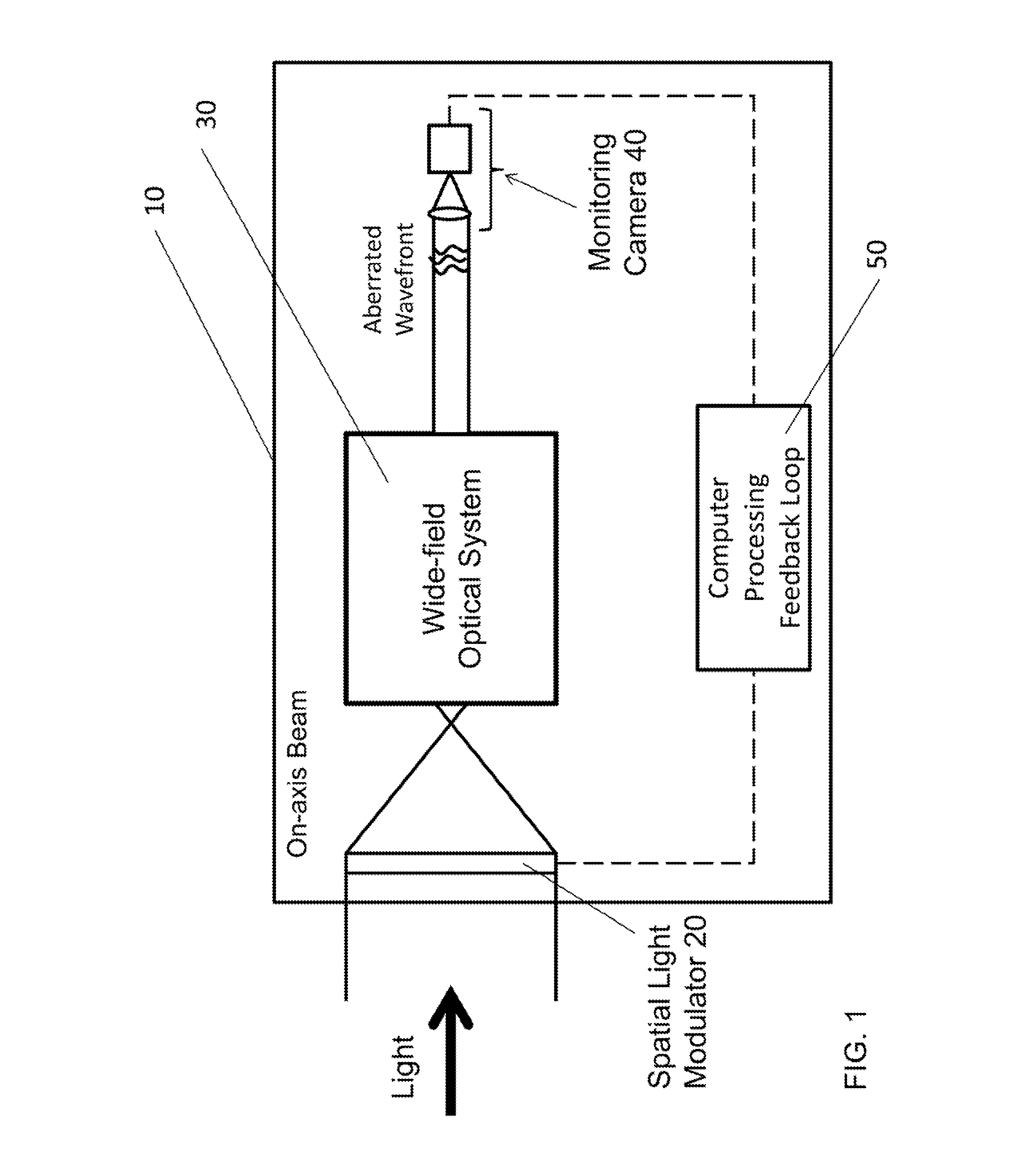
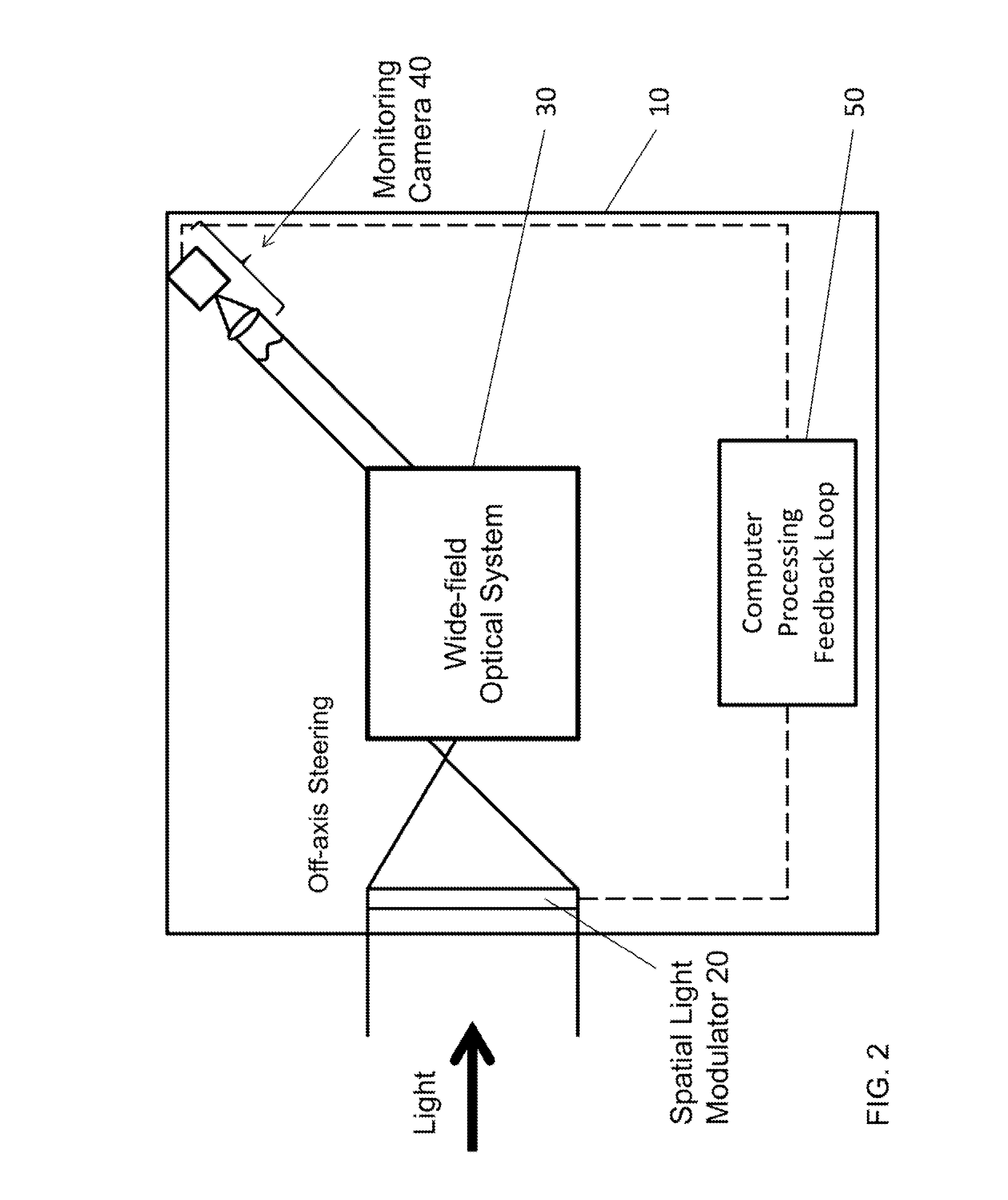
[0017]An embodiment of the present invention includes an apparatus 10, as shown by way of illustration in FIGS. 1 and 2. The apparatus includes a standard spatial light modulator 20, a standard wide-field optical system 30, the wide-field optical system including at least one optical system aberration; and a standard camera 40. The wide-field optical system 30 collimates a light beam toward the camera 40. The camera 40 communicates with the spatial light modulator 20 via a feedback loop 50 that pre-corrects for the at least one optical system aberration. Optionally, the wide-field optical system 30 includes a front focal point, the spatial light modulator 20 steering a focused light beam to the front focal point of the wide-field optical system. Optionally, the wide-field optical system 30 angularly magnifies the steered light beam from the spatial light modulator 20.

[0018]Optionally, the spatial light modulator 20 includes a reflective spatial light modulator, a transmissive spatia...


PUM


Abstract

A method and apparatus for simultaneous spatial light modulator beam steering and system aberration correction. The apparatus includes a spatial light modulator, a wide-field optical system, the wide-field optical system including at least one optical system aberration; and a camera. The wide-field optical system collimates a light beam toward the camera. The camera communicates with the spatial light modulator via a feedback loop that pre-corrects for the at least one optical system aberration.

Description

CROSS-REFERENCE TO RELATED APPLICATIONS[0001]This application claims the benefit of U.S. Provisional Application 62 / 012,536 filed on Jun. 16, 2014.BACKGROUND OF THE INVENTION[0002]It is well known that mechanically rotating mirrors can redirect and steer optical beams. A fast steering mirror can be used to scan the beam while an adaptive optics element (e.g., a spatial light modulator) can be used to correct residual optical aberrations. See, e.g., U.S. Pat. No. 7,742,213 to Potsaid et al.; and B. Potsaid, L. I. Rivera, and J. T. Y. Wen, “Adaptive Scanning Optical Microscope (ASOM): large field of view and high resolution imaging using a MEMS deformable mirror—art. no. 646706,” MEMS Adaptive Optics 6467, 46706-46706 (2007), both incorporated herein by reference. U.S. Pat. No. 7,742,213 to Potsaid et al. discloses an imaging system that uses a steering mirror to select the field of view and an “adaptive optics element” to compensate for optical aberrations. The parallel stochastic gr...

Claims


Application Information

Patent Timeline
Patent Type & Authority Applications(United States)
IPC IPC(8): H04N5/238G02B27/10H04N5/232G02B27/30
CPCH04N5/238H04N5/23238G02B27/10G02B27/30G02B27/0025G02B26/06H04N23/81
Inventor WATNIK, ABBIE T.CASSELLA, VINCENT A.
Owner THE UNITED STATES OF AMERICA AS REPRESENTED BY THE SECRETARY OF THE NAVY
Why Eureka
Try Eureka