Fixing unit of plate-shaped member, pvd processing apparatus and fixing method of plate-shaped member

Active Publication Date: 2015-12-24
TOKYO ELECTRON LTD
View PDF2 Cites 1 Cited by
  • Summary
  • Abstract
  • Description
  • Claims
  • Application Information

AI Technical Summary

Benefits of technology

[0010]In view of the above, the disclosure provides a fixing unit for fixing a plate-shaped member which can place the plate-shaped member while preventing deformation of the plate-shaped member due to thermal expansion, a PVD processing apparatus, and a fixing method for fixing a plate-shaped member.
[0011]In accordance with a first aspect of the present invention, there is provided a fixing unit for fixing a plate-shaped member to a fixing base member, the fixing unit including: a pressing unit configured to press the plate-shaped member toward the fixing base member; and a plurality of positioning units, installed at the fixing base member to be in contact with side surfaces of the plate-shaped member, and configured to place the plate-shaped member with respect to the fixing base member, wherein each of the positioning units includes: a shaft to be installed at the fixing base member in a direction perpendicular to a surface of the fixing base member; and a slide part movable along the shaft, and wherein the slide part includes a contact part configured to be in contact with one of the side surfaces of the plate-shaped member and a clearance part formed on the contact part to have a smaller width, in a direction parallel to the surface of the fixing base member, than that of the contact part.
[0012]In accordance with a second aspect of the present invention, there is provided a PVD processing apparatus for performing PVD processing on a substrate, the apparatus including: a chamber having a processing space therein; a target that is a plate-shaped member exposed to the processing space; a shutter member having an opening, and disposed between the processing space and the target; a fixing base member provided at the chamber; and a fixing unit configured to fix the target to the fixing base member, wherein the fixing unit includes: a pressing unit for pressing the target against the fixing base member; a plurality of positioning units installed at the fixing base member to be in contact with side surfaces of the target, the positioning units serving to place the target with respect to the fixing b

Problems solved by technology

If the target is not exactly positioned with respect to the shield member, the gap between the target and an edge of the shield member becomes excessively small.
However, when the positioning blocks are made to be in contact with the four side surfaces of the target, thermal expansion of the target during the sputtering is res

Method used


Image

  • Fixing unit of plate-shaped member, pvd processing apparatus and fixing method of plate-shaped member
  • Fixing unit of plate-shaped member, pvd processing apparatus and fixing method of plate-shaped member
  • Fixing unit of plate-shaped member, pvd processing apparatus and fixing method of plate-shaped member

Examples


Example

[0021]Hereinafter, embodiments will be described with reference to the accompanying drawings.

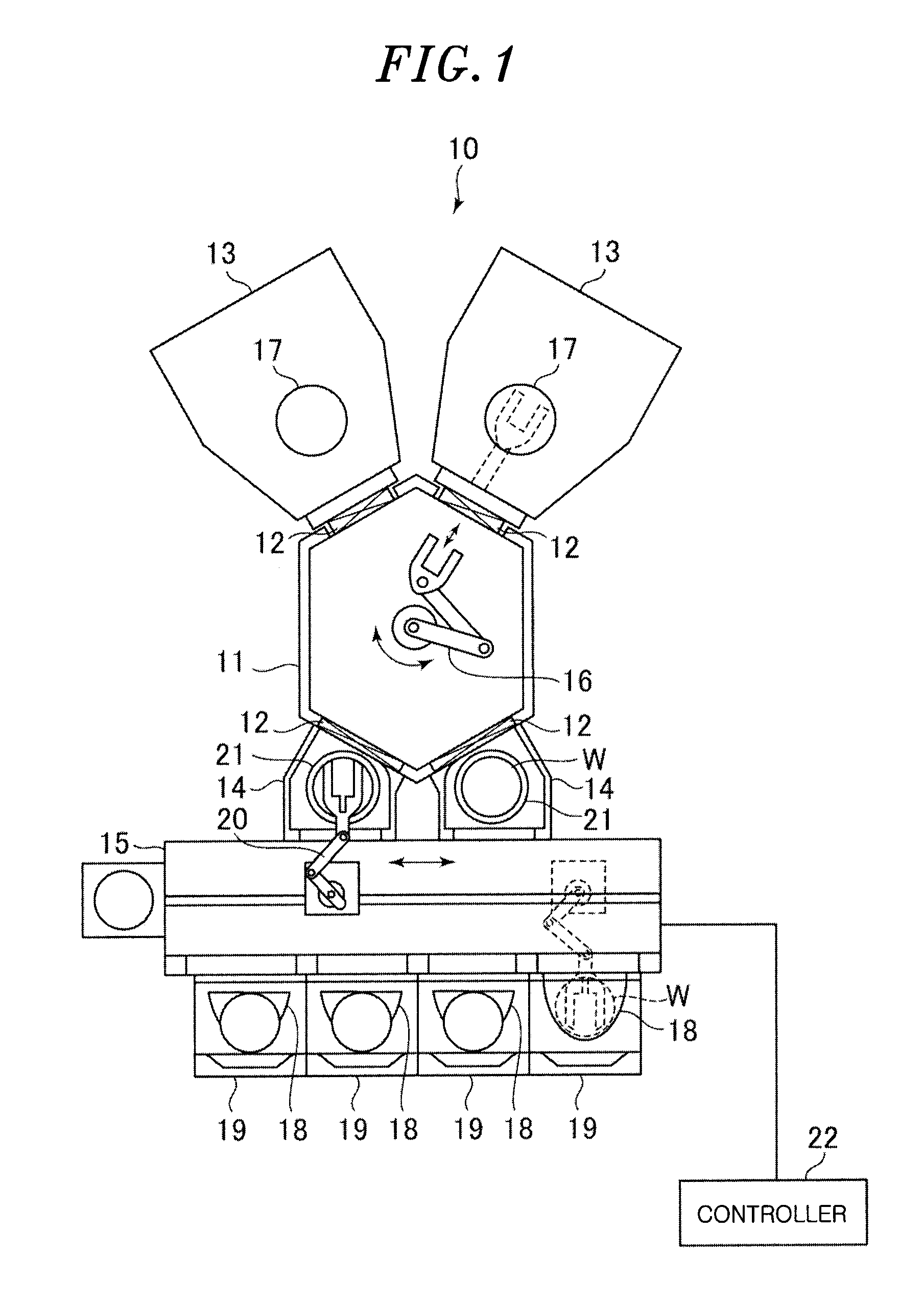
[0022]FIG. 1 is a top view schematically showing a configuration of a substrate processing system including a process module as a PVD processing apparatus according to an embodiment. In FIG. 1, a hidden part of the configuration is illustrated for better understanding.

[0023]Referring to FIG. 1, a substrate processing system 10 includes: a transfer module 11; two process modules 13 connected to the transfer module 11 via gate valves 12; two load-lock modules 14 connected to the transfer modules 11 via gate valves 12; and a loader-module 15 connected to the transfer module 11 through the load-lock modules 14.

[0024]The transfer module 11 is an approximately hexagonal transfer chamber when seen from the top. Provided in the transfer module 11 is a transfer arm 16 for transferring a wafer W between each of the process modules 13 and each of the load-lock modules 14. An inside of the transfer modu...


PUM


Abstract

A fixing unit fixes a plate-shaped member to a fixing base member. The fixing unit includes: a pressing unit configured to press the plate-shaped member toward the fixing base member; and a plurality of positioning units, installed at the fixing base member to be in contact with side surfaces of the plate-shaped member, and configured to place the plate-shaped member with respect to the fixing base member. Each of the positioning units includes: a shaft to be installed at the fixing base member; and a slide part movable along the shaft, and the slide part includes a contact part to be in contact with one of the side surfaces of the plate-shaped member and a clearance part formed on the contact part to have a smaller width than that of the contact part.

Description

CROSS-REFERENCE TO RELATED APPLICATION[0001]This application claims priority to Japanese Patent Application No. 2014-126558 filed on Jun. 19, 2014, the entire contents of which are incorporated herein by reference.FIELD OF THE INVENTION[0002]The disclosure relates to a fixing unit for a plate-shaped member, a PVD (e.g., physical vapor deposition) processing apparatus, and a fixing method for a plate-shaped member.BACKGROUND[0003]In a PVD film forming apparatus for performing a PVD film forming process on a substrate, e.g., a semiconductor wafer (hereinafter, referred to simply as “wafer”), a target of a film forming material is provided in a processing chamber. The PVD film forming apparatus forms a thin film of the film forming material on the wafer by generating plasma in a processing space, sputtering the target by the plasma, and depositing scattered sputter particles of the film forming material on the wafer. The target is exposed to the processing space and fixed above the waf...

Claims


Application Information

Patent Timeline
IPC IPC(8): H01L27/146
CPCG03G15/2064C23C14/3407H01J37/3435
Inventor YOKOHARA, HIROYUKIORIMOTO, SHINJISONE, HIROSHISUZUKI, NAOYUKI
Owner TOKYO ELECTRON LTD
Why Eureka
Try Eureka