Gate driving circuit

a driving circuit and gate technology, applied in the field of liquid crystal display driving technology, can solve the problems of high potential for a long time, complete disassembly of the whole gate driving circuit, and abnormal display of the liquid crystal display device, and achieve the effects of low leakage current, high reliability and stability

Active Publication Date: 2015-12-24
SHENZHEN CHINA STAR OPTOELECTRONICS TECH CO LTD
View PDF5 Cites 20 Cited by
  • Summary
  • Abstract
  • Description
  • Claims
  • Application Information

AI Technical Summary

Benefits of technology

[0015]Aiming at the above-mentioned problem, the present disclosure proposes a

Problems solved by technology

In a serious case, a power supply chip for providing the first power supply VSS1 and the second power supply VSS2 could be burnt out as being in a working state of a negative voltage against a positive current, due to the leak current, for a long time, so that abnormal display of the liquid crystal display device is caused.
Such leak current is increased particularly during high-temperature operation state, and in a worse case, it causes the voltage holding function of the pull-down holding part 500 completely failure, so that the whole gate driving circuit is completely disabled.
Due to lack of an effective dis

Method used


Image

  • Gate driving circuit
  • Gate driving circuit
  • Gate driving circuit

Examples


Embodiment Construction

[0112]In order to make the technical contents disclosed by the present disclosure more detailed and complete, the composition structure and operation principle of an existing gate driving unit and the technical problem to be solved urgently thereof will be first illustrated in detail below with reference to the accompanying drawings.

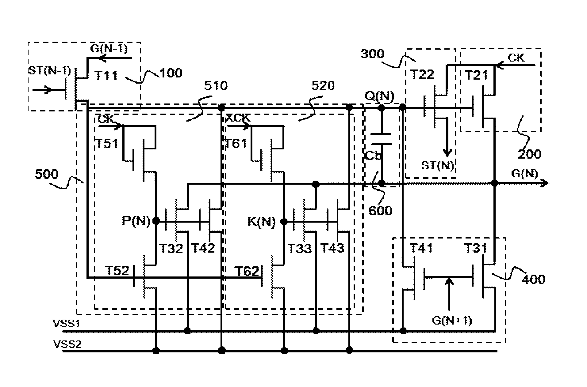
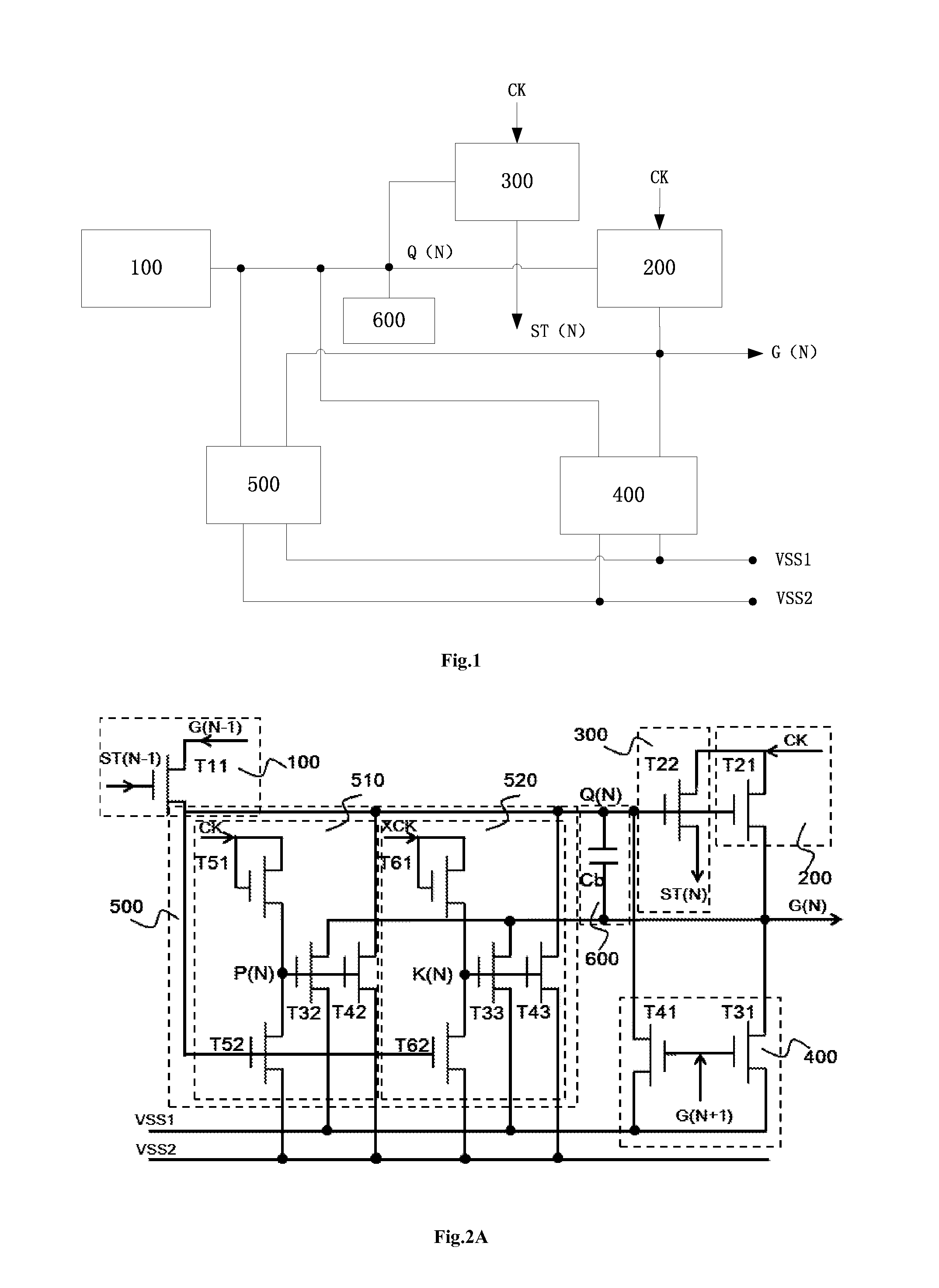
[0113]FIG. 2A shows a schematic diagram of circuit structure of a gate driving unit disclosed in a Chinese patent application No. 103559867A. This figure only shows a gate driving unit which is denoted as N. For convenience of illustration, a previous one of this gate driving unit is denoted as N−1, and the one after this gate driving unit is marked as N+1, and so on.

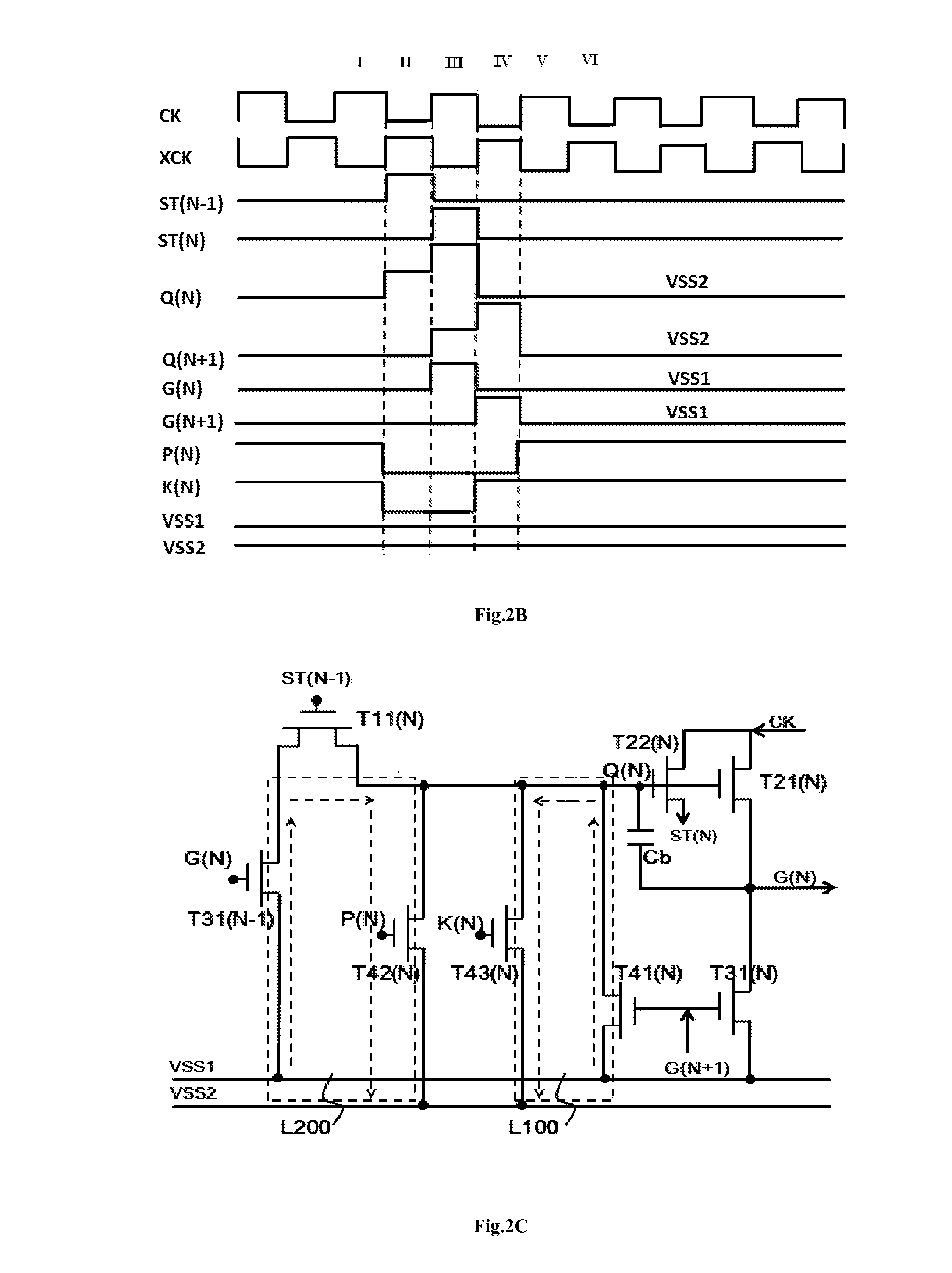
[0114]The composition structure and operation principle of a Nth gate driving unit will be illustrated in detail below in combination with a signal time sequence diagram shown in FIG. 2B.

[0115]A pull-up control part 100 includes a transistor T11. The gate of the transistor T11 receives a tra...


PUM


Abstract

The present invention relates to a gate driving circuit including a multiple of gate driving units. Each of the gate driving units comprises a pull-up control part, a pull-up part, a transfer part, a key pull-down part, a pull-down holding part and a boost part. In this case, the key pull-down part and the transfer part are configured, respectively, to pull potential on a gete signal output end down to and hold potentials on the control ends of the pull-up part and the transfer part at a potential of the first power supply or the second power supply, and also to pull potential on the output end of the transfer part ransfer signal down to and/or hold at a potential of the second power supply, wherein the potential of the second power supply is lower than that of the first power supply.

Description

[0001]The present application claims benefit of Chinese Patent Application No. 201410228218.2, filed in May 27, 2014 and entitled “Gate driving circuit”, the disclosure of which is expressly incorporated by reference herein in its entirety.FIELD OF THE INVENTION[0002]The present disclosure relates to a liquid crystal display driving technology, in particular to a gate driving circuit of a liquid crystal display.BACKGROUND OF THE INVENTION[0003]Generally, a liquid crystal display device includes a plurality of pixel units, as well as a gate driving circuit (Gate IC) and a source driving circuit (Source IC) which are used for driving these pixel units. Wherein, the gate driving circuit consists of a plurality of cascaded gate driving units. These gate driving units sequentially output gate signals through gate lines coupled thereto to control corresponding switching transistors in a display area to be turned on row by row, so that data signals output by the source driving circuit are ...

Claims


Application Information

Patent Timeline
IPC IPC(8): G09G3/36
CPCG09G3/20G09G3/36G09G2320/0219G09G2330/04G09G2310/0286G09G2310/08G09G2310/0267
Inventor XIAO, JUNCHENG
Owner SHENZHEN CHINA STAR OPTOELECTRONICS TECH CO LTD
Why Eureka
Try Eureka