Nerve cuff stimulation electrode, control device for a vagus nerve stimulation system, and vagus nerve stimulation system

Active Publication Date: 2015-12-31
BIOTRONIK SE & CO KG
View PDF2 Cites 9 Cited by
  • Summary
  • Abstract
  • Description
  • Claims
  • Application Information

AI Technical Summary

Benefits of technology

[0036]The nerve cuff stimulation electrode, the control device and the Vagus Nerve Stimulation (VNS) system comprising both, the nerve cuff stimulation electrode and the control device according to an embodiment of the invention, each advance the state-of-the-art in cervical VNS for CHF treatment by providing a system for continuous monitoring of venous and arterial pressures, cardiac timing for arrhythmia detection, in particular patient sleeping angles and parameters relevant to the diagnostics of OSA, without requiring endocardial leads.
[0037]Each vagus nerve is situated posteriorly between the Common Carotid Artery (CCA) and the Internal Jugular Vein (IJV) in the carotid sheath, a fibrous connective tissue that surrounds the vascular compartment of the neck. The nerve cuff stimulation electrode of the present invention takes advantage of this proximity and integrates a pulsation sensor (and ass

Problems solved by technology

Chronic implantable VNS for CHF apparatuses in the prior art generally lack monitoring capabilities for disease progression, or these are limited to cardiac timing and transthoracic impedance measurements which require leads in the heart.
Apparatuses in the prior art lack, in particular, the capability of measuring arterial or venous pressure waveforms, which are critical parameters in the assessment of complications related to CHF.
VNS for CHF apparatuses in the prior art lack these measu

Method used


Image

  • Nerve cuff stimulation electrode, control device for a vagus nerve stimulation system, and vagus nerve stimulation system
  • Nerve cuff stimulation electrode, control device for a vagus nerve stimulation system, and vagus nerve stimulation system
  • Nerve cuff stimulation electrode, control device for a vagus nerve stimulation system, and vagus nerve stimulation system

Examples


Embodiment Construction

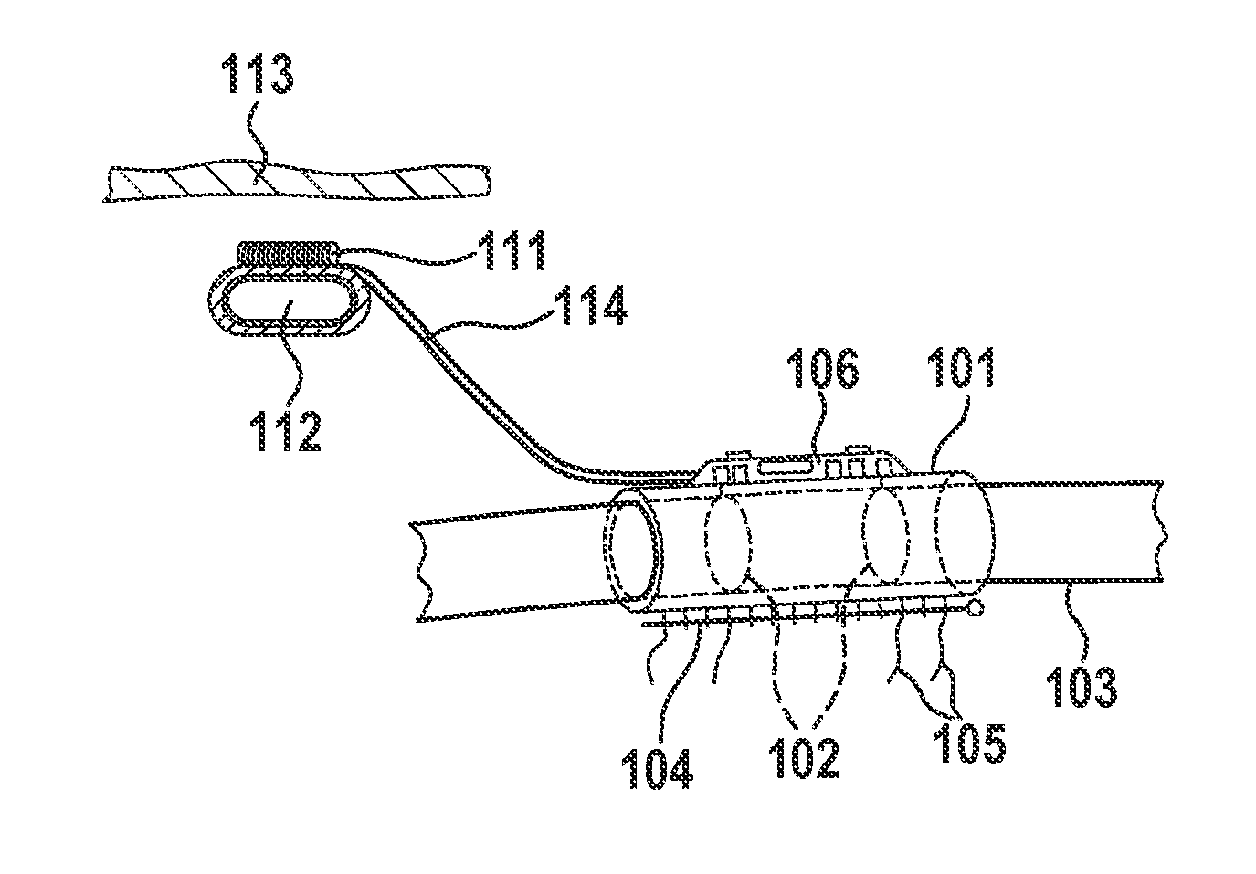
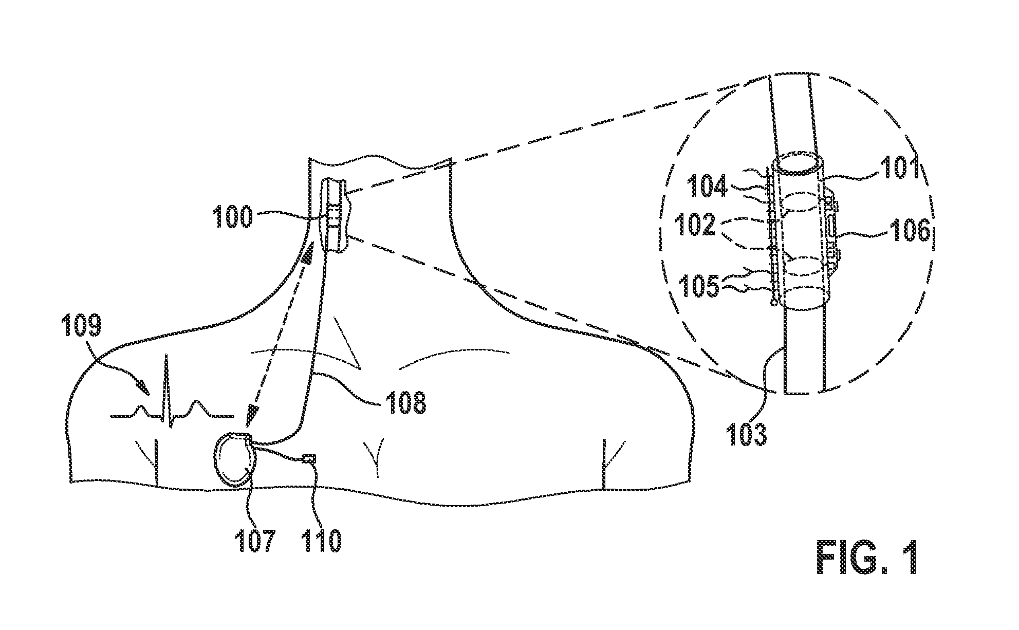
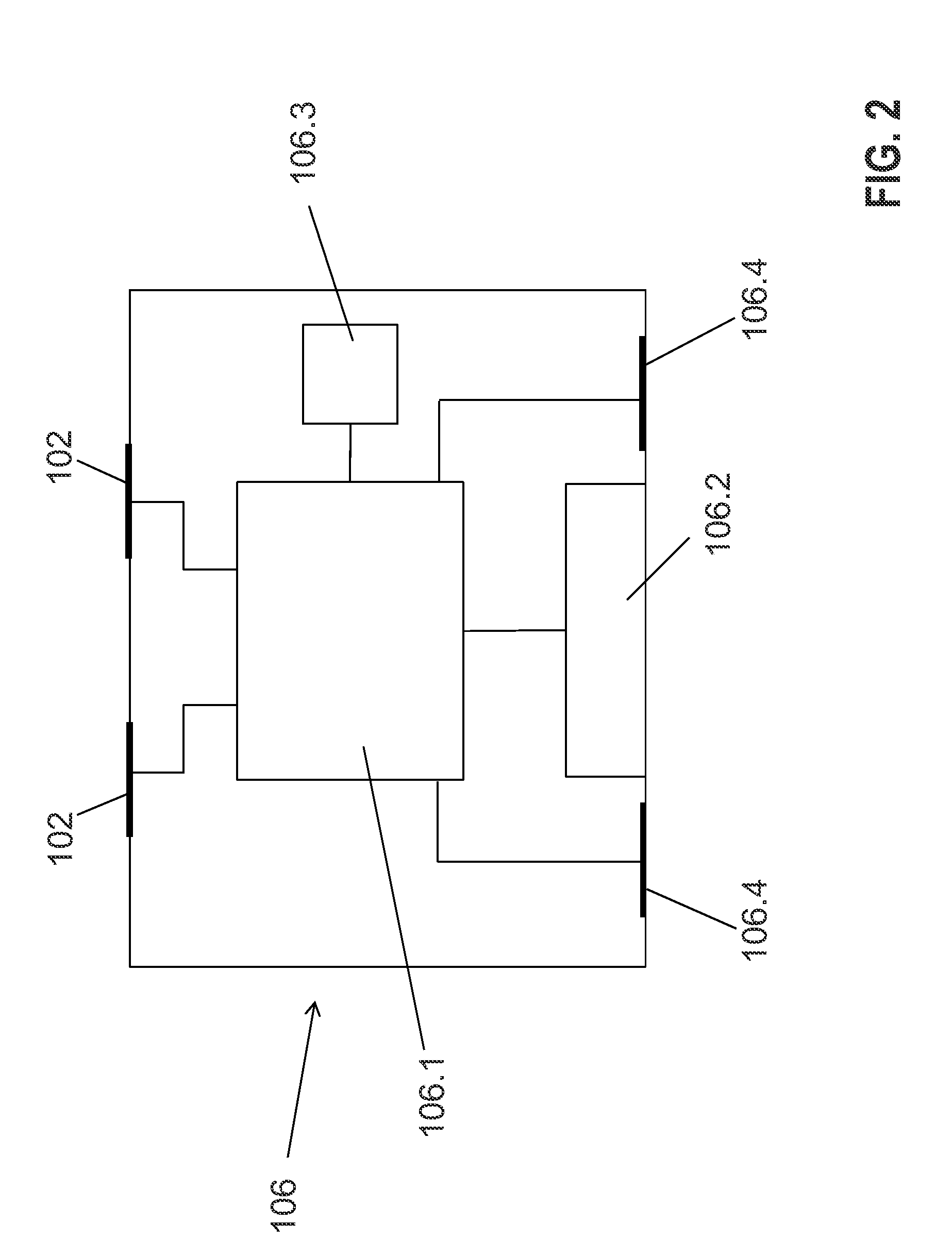
[0053]According to an exemplary embodiment of the invention as shown in FIG. 1, a nerve cuff stimulation electrode 100 is constructed, using a silicone rubber tube 101, with at least two exposed Pt / Ir (or equivalent material) ring contacts 102 in its interior wall in contact with the vagus nerve 103 surface, and a closing structure 104. The cuff stimulation electrode 100 can be self-coiling, or it may include other closing mechanisms, such as a piano hinge with a nylon suture. Biocompatible strings 105 are built on the cuff stimulation electrode 100 outer wall to open it for easy implantation around the nerve 103. Electronic circuitry 106, which may include a pulsation sensor, a triaxial accelerometer, and associated front-end electronic circuitry, is built on the cuff stimulation electrode 100 outer wall and / or associated assembly structures.

[0054]In an exemplary embodiment, the ring contacts 102 are replaced by multiple contacts around the nerve 103. Local bipolar stimulation betw...


PUM


Abstract

A nerve cuff stimulation electrode for cervical VNS is provided and configured to be arranged so as to at least partially surround or enclose one of the vagus nerves. The cuff stimulation electrode has at least two contacts configured to deliver electric stimulation pulses to a vagus nerve. The cuff stimulation electrode further has or may be attached or connected to a tilt sensor, a kinematic sensor, and/or a pulsation sensor configured to generate a signal representative of arterial and venous pressures. The implantable tilt sensor is configured to output a posture signal indicating a patient's posture, thus allowing discrimination between supine and semi-recumbent or erect postures.

Description

[0001]This nonprovisional application claims priority to U.S. Provisional Application No. 62 / 017,282, which was filed on Jun. 26, 2014, and which is herein incorporated by reference.BACKGROUND OF THE INVENTION[0002]1. Field of the Invention[0003]The present invention relates to a nerve cuff stimulation electrode, a control device for a Vagus Nerve Stimulation (VNS) system, and a VNS system.[0004]2. Description of the Background Art[0005]Vagus Nerve Stimulation (VNS) systems and methods are inter alia disclosed in U.S. Pat. No. 8,401,640, US 2013 / 0184773 and U.S. Pat. No. 8,473,068.[0006]Cervical VNS may be used for the treatment of Congestive Heart Failure (CHF).[0007]Conventional chronic implantable apparatuses for VNS for the treatment of CHF generally involve implanting a cervical nerve cuff electrode for stimulation that connects via wires to an Implantable Pulse Generator (IPG) in a patient's chest. A standard pacemaker sensing lead in the ventricle has been disclosed for the p...

Claims


Application Information

Patent Timeline
IPC IPC(8): A61B5/00A61B5/0452A61B5/11A61B5/042
CPCA61B5/0205A61B5/02125A61B5/0215A61B5/6877A61N1/36053A61B5/002A61N1/0556A61N1/28A61B5/1116
Inventor BARU, MARCELOKIBLER, ANDREW B.DABNEY, WARRENLIAN, JIEMOULDER, CHRISTOPHERMUESSIG, DIRK
Owner BIOTRONIK SE & CO KG
Why Eureka
Try Eureka