Systems and Methods Related to Coupling an Energy Harvester to Exercise Equipment

a technology of energy harvester and exercise equipment, applied in the field of exercise equipment, can solve the problems of objectionable exercise feel for users, undetectable ripple forces and torques, and methods that have generally had substantial performance limitations, and achieve the effect of increasing the overall mass of the energy harvester

Inactive Publication Date: 2015-12-31
STRENGTH COMPANION
View PDF5 Cites 23 Cited by
  • Summary
  • Abstract
  • Description
  • Claims
  • Application Information

AI Technical Summary

Benefits of technology

[0012]According to a further aspect of an embodiment of a system according to the present invention, the electrical generator may be a part of an energy harvester that has a frame and a reel rotatably supported by the frame, wherein the cord extends about an outer circumference of the reel. The reel my be fixed to a second shaft that is rotatably supported by the frame. The reel may include a housing radially at least partially surrounding an arbor secured to the frame, the reel substantially containing a biasing member anchored to the arbor and the housing. The biasing member may be a spring member, such as a constant (or near-constant) force spring, torsion spring, or other desirable biasing member that may be used to balance cord tension. The energy harvester may include a ballast mass coupled to its frame, the ballast mass may serve no other purpose but to increase the overall mass of the energy harvester.

Problems solved by technology

In exercise equipment that is of the strength training type, methods to produce electrical power by converting human input have been disclosed in prior literature, however the methods have generally had substantial limitations in performance.
For instance, prior systems and methods employ energy harvesters that couple directly and rigidly to a translating or rotating member of the equipment in a manner that may cause undesired ripple forces and torques.
That is, that arise during a process of electromechanical energy conversion are transmitted to the user, either through the seat or the user's grip, resulting in an objectionable exercise feel to the user.
The undesired forces also can result in the generation of objectionable acoustic noise, for example inducing vibrations in the lightly damped, mechanically stiff frame of exercise equipment that resonate at frequencies in the audible range.
The modifications required for one equipment type, (e.g., a biceps machine), may generally not be compatible with the other types.
Another drawback of prior art methods, especially methods that rely on engagement or attachment to existing equipment pulleys, is that they are not well-suited to strength equipment that incorporates independent motion arrangements (e.g., left and right bodily motion arrangements) with a common weight stack.
When a user selects a relatively low weight, for example 10 pounds, the friction force capacity between the main belt and pulley is generally insufficient to support the function of the energy harvester to produce power from the exercise motion.
Further, as safety is usually a critical issue, prior systems and methods fail to address adequately a failure in the generator or electronics of an energy harvester.
Such conditions may result in substantial torque applied to the generator shaft of the energy harvester, the torque is subsequently converted to a proportional force applied to the weight stack of the exercise equipment.
Generally, the resulting force associated with a failure condition can be large and sudden and therefore harmful to a user that has a grip and is engaged in an exercise motion.
For applications where the user has an exercise objective of rehabilitation or therapy, the occurrence of a large weight stack force is especially unacceptable.

Method used


Image

  • Systems and Methods Related to Coupling an Energy Harvester to Exercise Equipment
  • Systems and Methods Related to Coupling an Energy Harvester to Exercise Equipment
  • Systems and Methods Related to Coupling an Energy Harvester to Exercise Equipment

Examples


Embodiment Construction

[0032]Although the disclosure hereof is detailed and exact to enable those skilled in the art to practice the invention, the physical embodiments herein disclosed merely exemplify the invention which may be embodied in other specific structures. While the preferred embodiment has been described, the details may be changed without departing from the invention, which is defined by the claims.

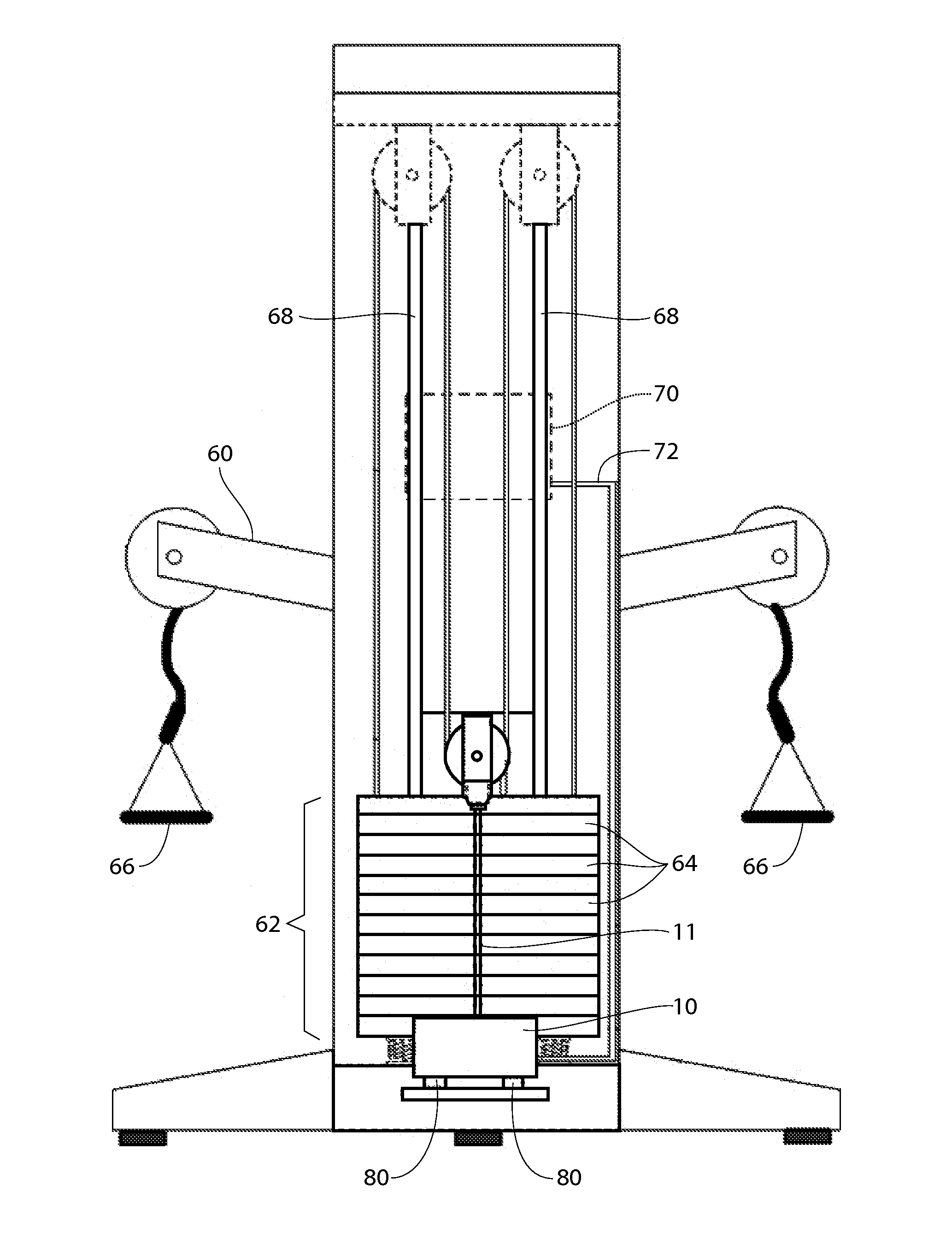
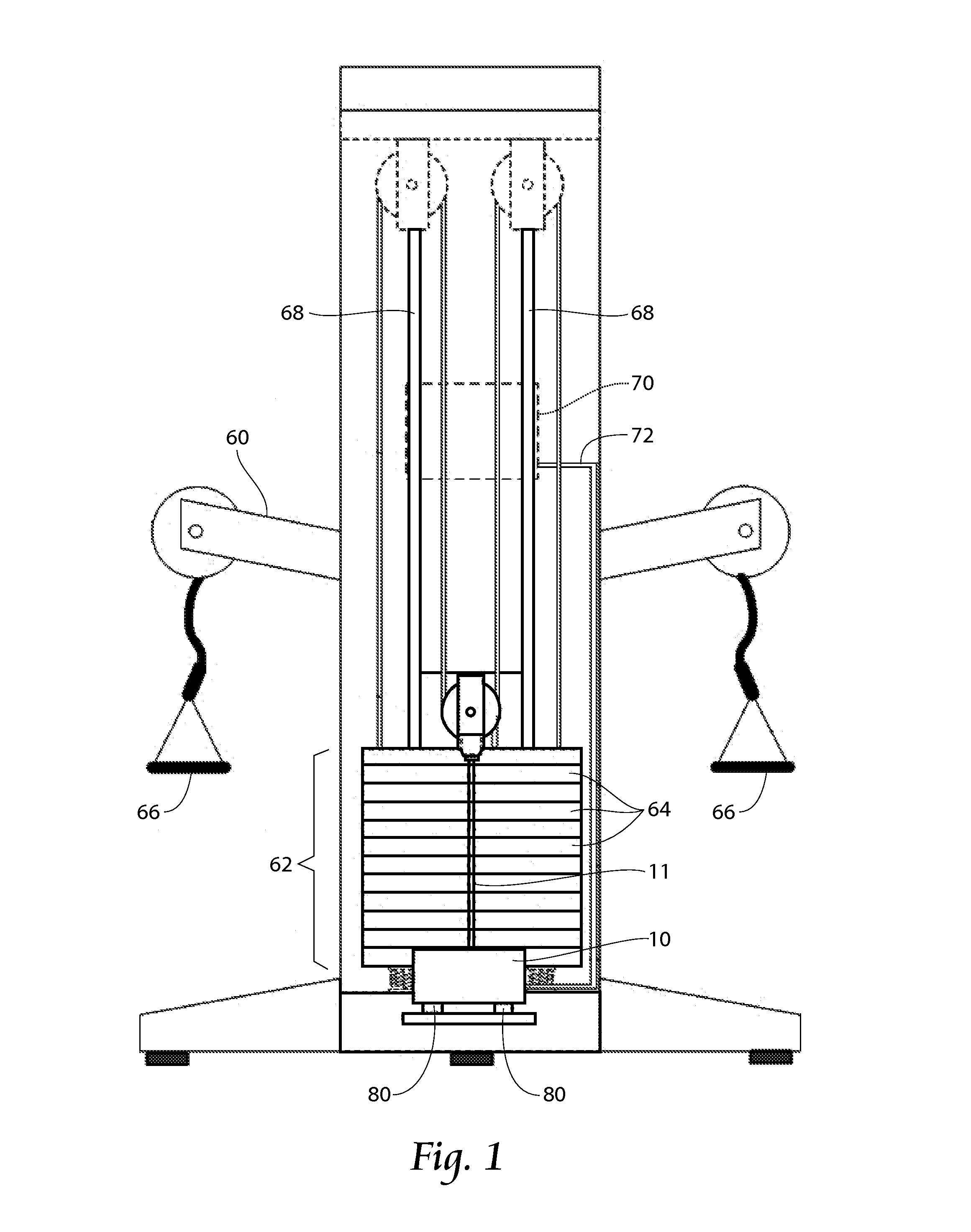
[0033]Referring now to the figures, FIG. 1 depicts an energy harvester 10 mechanically coupled to an exercise equipment machine 60 by a flexible cable, wherein the harvester 10 produces electrical power during an exercise motion performed by a user of the machine 60. The energy harvester 10 provides electrical power to an electronics unit 70 or other electrical storage element (e.g. capacitor or battery) or load (e.g., light(s), heating elements, battery chargers, etc.), which may be electrically connected to the harvester 10 by an electrical cord 72. As is generally known, strength training machi...


PUM


Abstract

A system and method for mechanically coupling an energy harvester to strength training type exercise equipment is disclosed. An energy harvester with unwanted vibration forces is mechanically isolated from exercise equipment by a system comprising a plurality of mechanically compliant vibration isolators and a ballast mass; a flexible cord, pre-loaded with a near constant force spring is used to transmit motion from the weight stack to the energy harvester; the flexible cord has a force limiting feature to pre-excessive force from being transmitted from the energy harvester to the weight stack during an exercise motion.

Description

RELATED APPLICATIONS[0001]This application claims the benefit of co-pending U.S. Provisional Patent Application Ser. No. 61 / 935,853, filed 5 Feb. 2014, and entitled “Exercise Equipment With Coupling To An Energy Harvester,” which is incorporated herein by reference in its entirety.[0002]This application also claims the benefit of co-pending U.S. Provisional Patent Application Ser. No. 61 / 941,455, filed 18 Feb. 2014, and entitled “Exercise Equipment With Coupling To An Energy Harvester,” which is incorporated herein by reference in its entirety.BACKGROUND OF THE INVENTION[0003]This invention relates generally to the field of exercise equipment, and more specifically, exercise equipment having an electrical generating means. Systems and methods to produce electrical power derived from a human exercise motion, herein referred to as human-input, are known and have been reduced to practice in commercial exercise equipment products. Commercial has generally been limited to exercise produc...

Claims


Application Information

Patent Timeline
Patent Type & Authority Applications(United States)
IPC IPC(8): A63B21/005H02K7/18A63B21/062
CPCA63B21/0628H02K7/1853A63B71/0054A63B21/025A63B21/153A63B21/157A63B23/03533A63B24/0087F03G7/08H02J3/00A63B2071/0063A63B2071/0081A63B2071/065A63B2209/08A63B2209/10A63B2220/17A63B2220/20A63B2225/09A63B2225/50A63B21/169A63B21/0054F03G5/06A63B21/4043A63B21/4035F03G1/02H02J7/1407H02J50/001F03G1/026F03G5/065
Inventor OTEMAN, DAVID G.LEE, JIN W.
Owner STRENGTH COMPANION
Why Eureka
Try Eureka