Test pattern for feature cross-sectioning

Inactive Publication Date: 2015-12-31
GLOBALFOUNDRIES INC
View PDF9 Cites 1 Cited by
  • Summary
  • Abstract
  • Description
  • Claims
  • Application Information

AI Technical Summary

Benefits of technology

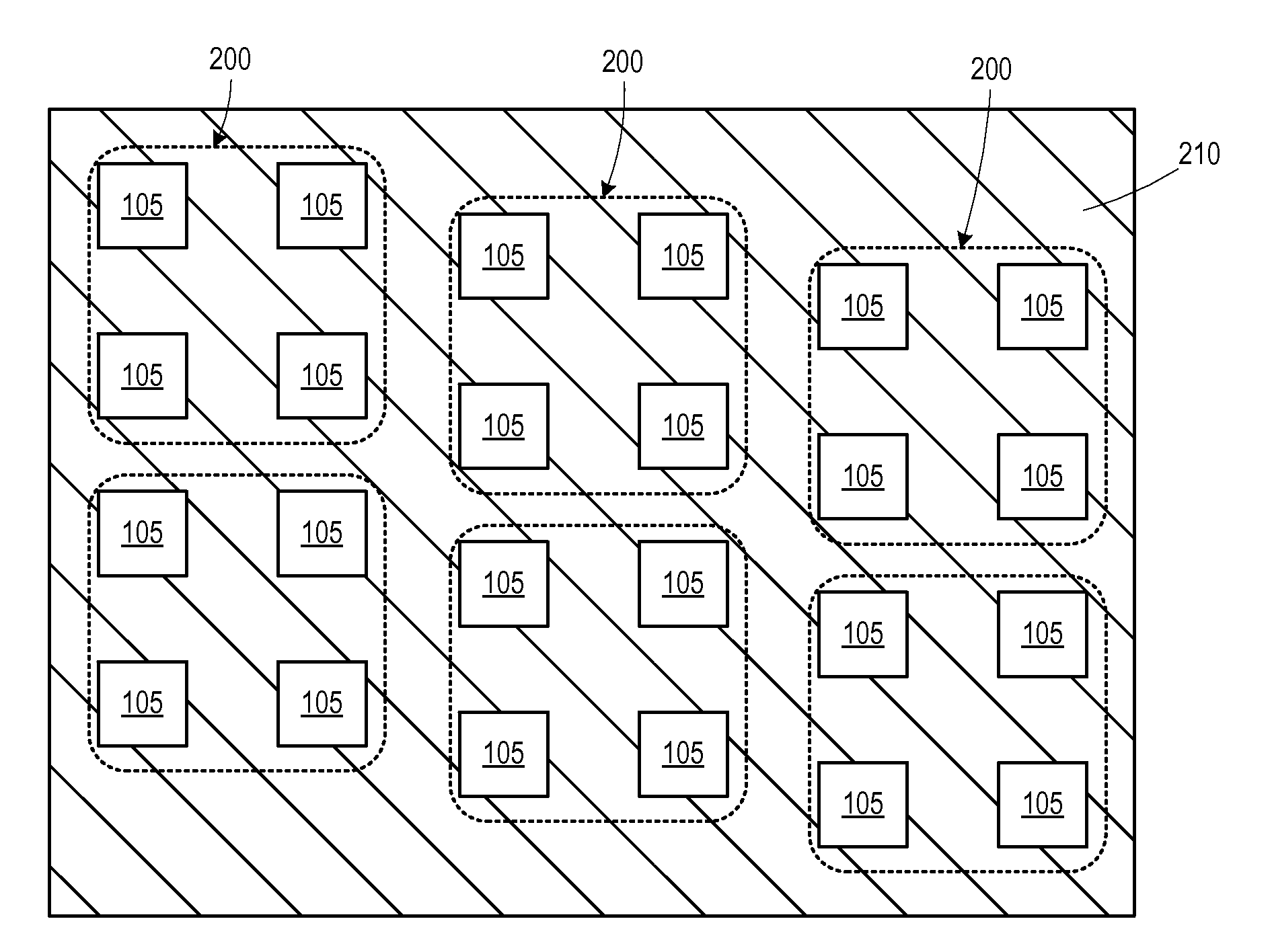
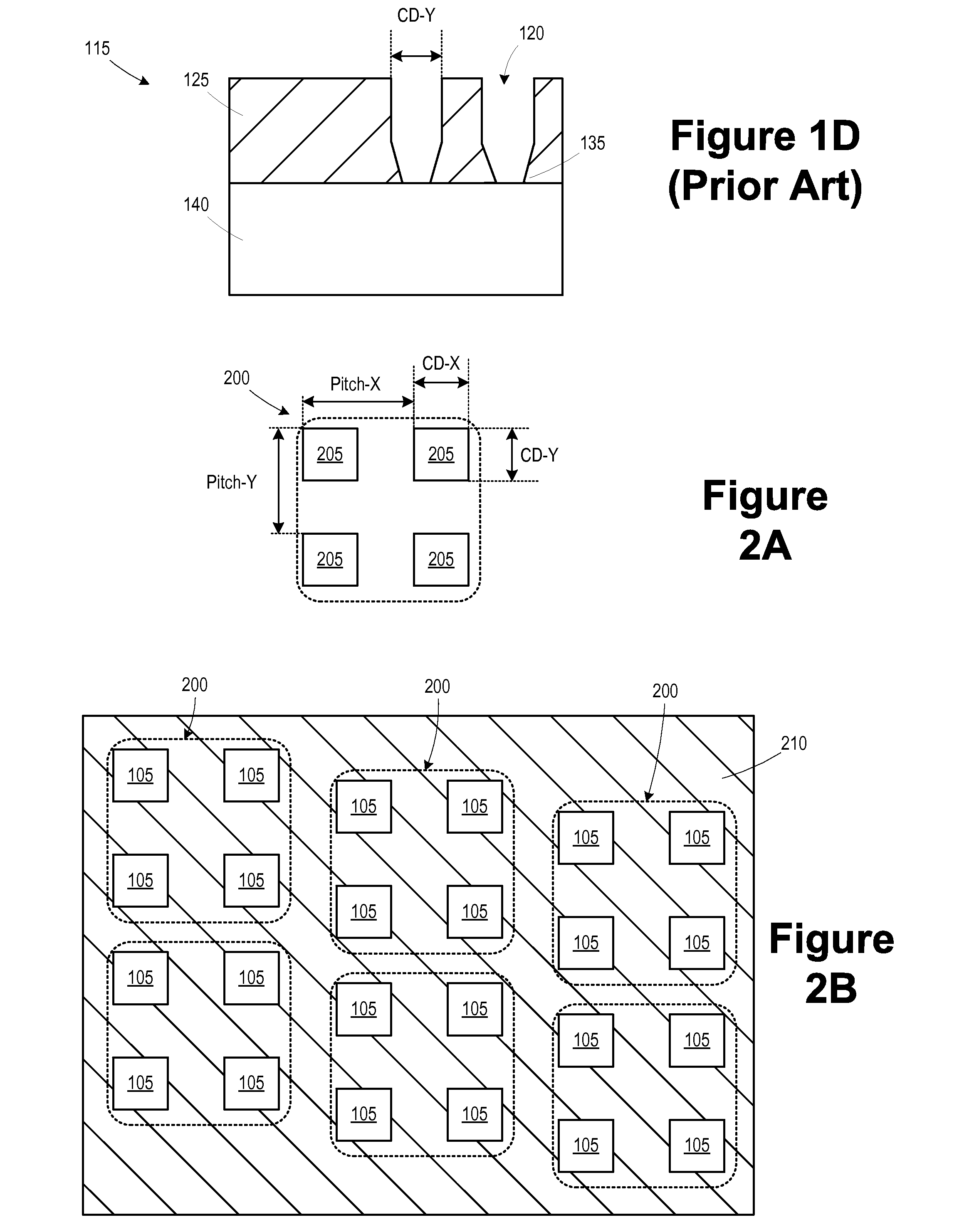
The present invention provides methods of forming substrates with patterns and resulting semiconductor devices. A method includes forming multiple instances of a pattern on a substrate with features offset from one another in a second direction. The substrate is then cleaved along a cleavage line, and the critical dimension of a feature in the pattern is measured. The technical effect of this invention is the ability to precisely create patterns on substrates and measure their critical dimensions. This is useful in the development of semiconductor devices.

Problems solved by technology

Underexposing the features can result in the incomplete formation of the features in the photoresist masking layer for forming the contact openings.
When a subsequent contact etch is performed, the pattern is not effectively transferred to the dielectric or other layers below.
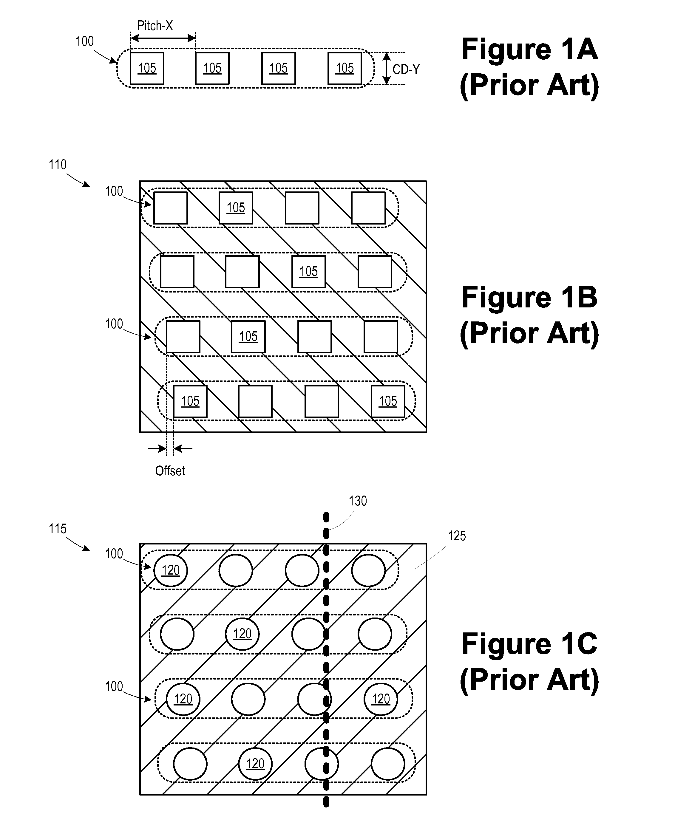
First, it only allows the measurement of a CD in one direction.
One potential drawback of the current art, in which a pattern shift for neighboring contacts is applied in the x- and y-directions, is that if the shifts are large enough, then the cleave pattern will deviate significantly from the original non-shifted pattern.

Method used


Image

  • Test pattern for feature cross-sectioning
  • Test pattern for feature cross-sectioning
  • Test pattern for feature cross-sectioning

Examples


Embodiment Construction

[0026]Various illustrative embodiments of the invention are described below. In the interest of clarity, not all features of an actual implementation are described in this specification. It will of course be appreciated that in the development of any such actual embodiment, numerous implementation-specific decisions must be made to achieve the developers' specific goals, such as compliance with system-related and business-related constraints, which will vary from one implementation to another. Moreover, it will be appreciated that such a development effort might be complex and time-consuming, but would nevertheless be a routine undertaking for those of ordinary skill in the art having the benefit of this disclosure.

[0027]The present subject matter will now be described with reference to the attached figures. Various structures, systems and devices are schematically depicted in the drawings for purposes of explanation only and so as to not obscure the present disclosure with details ...


PUM


Abstract

A method includes forming a first plurality of instances of a first pattern on a substrate. The first pattern includes a plurality of features defining a first spacing between features in a first direction. The instances in the first plurality are offset from one another at least in a second direction other than the first direction. The substrate is cleaved along a cleavage line. At least a first critical dimension of a feature in the first plurality of instances intersected by the cleavage line is measured.

Description

BACKGROUND OF THE INVENTION[0001]1. Field of the Invention[0002]The present disclosure generally relates to the fabrication of integrated circuits, and, more particularly, to reticles for forming test patterns for feature cross-sectioning and methods of using the reticles and wafers fabricated using the reticles.[0003]2. Description of the Related Art[0004]In modern integrated circuits, such as microprocessors, storage devices and the like, a very large number of circuit elements, especially transistors, are provided and operated on a restricted chip area. Immense progress has been made over recent decades with respect to increased performance and reduced feature sizes of circuit elements, such as transistors. However, the ongoing demand for enhanced functionality of electronic devices forces semiconductor manufacturers to steadily reduce the dimensions of the circuit elements and to increase the operating speed and reduce the power consumption of circuit elements. The continuing sc...

Claims


Application Information

Patent Timeline
IPC IPC(8): H01L21/66G01B11/00H01L21/78
CPCH01L22/12H01L21/78G01B11/002G03F1/44H01L22/30G03F7/70683G03F7/70625
Inventor CIVAY, DENIZ E.SCHLIEF, RALPH
Owner GLOBALFOUNDRIES INC
Why Eureka
Try Eureka