Centralized power distribution member for motor

a technology of centralized power distribution and motor, which is applied in the direction of dynamo-electric machines, electrical devices, windings, etc., can solve the problems of mounting constraints and inability to deal with mounting in terms of space, and achieve the effect of suppressing the enlargement of the annular holder and saving spa

Inactive Publication Date: 2015-12-31
SUMITOMO WIRING SYST LTD +1
View PDF8 Cites 11 Cited by
  • Summary
  • Abstract
  • Description
  • Claims
  • Application Information

AI Technical Summary

Benefits of technology

[0014]In this configuration, a narrower and more compact structure is obtained.
[0015]According to the centralized power distribution member of the present inven

Problems solved by technology

In the case of mounting the neutral point busbars into the annular holder, the windings of the aforementioned stator are generally arranged at an inner peripheral side of the

Method used


Image

  • Centralized power distribution member for motor
  • Centralized power distribution member for motor
  • Centralized power distribution member for motor

Examples


Embodiment Construction

[0029]One embodiment of the present invention is described based on FIGS. 1 to 13.

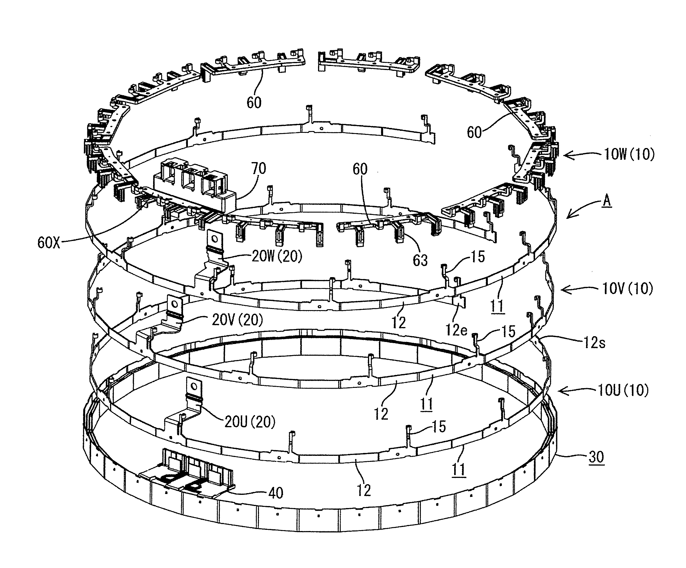
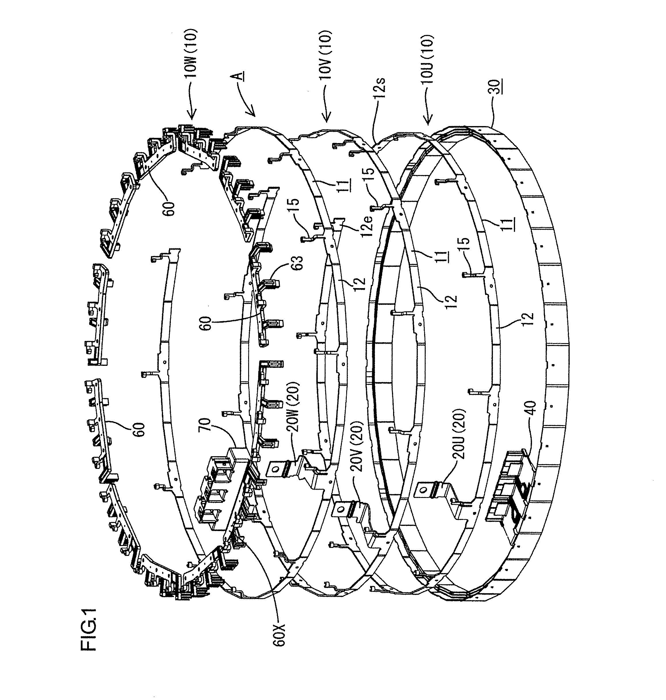
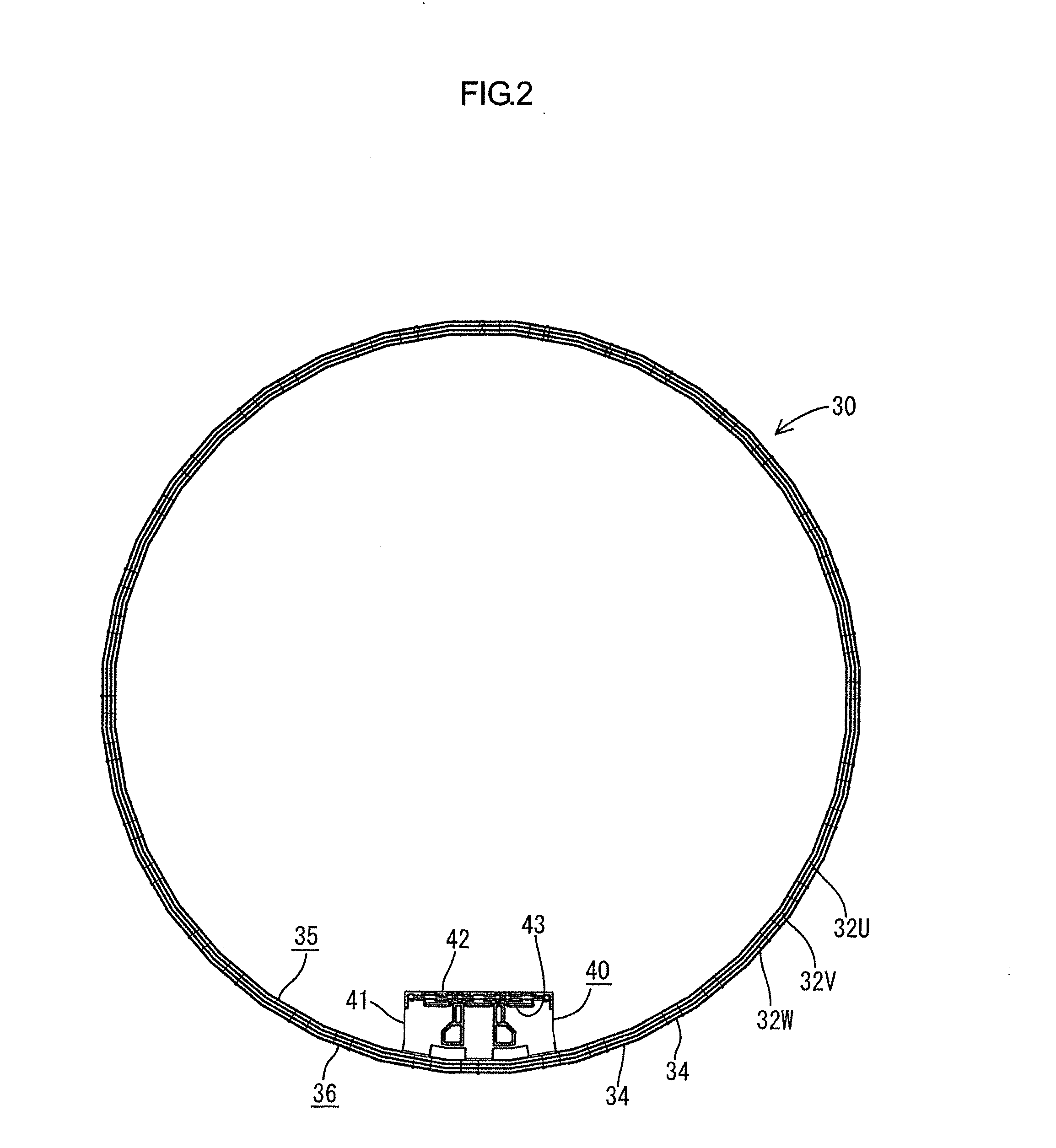
[0030]A motor of this embodiment is a three-phase alternating current brushless motor with 12 pole pairs to be mounted in a hybrid vehicle and is arranged, for example, in a narrow space between an engine and a transmission and includes a rotor (not shown) coaxially coupled to a horizontal crankshaft of the engine, an annular stator S (see FIG. 7) concentrically surrounding the rotor and an annular centralized power distribution member A concentrically surrounding the stator S. The stator S is composed of a plurality of magnetic poles (not shown) formed by winding coils on cores, the magnetic poles are arranged at fixed intervals along a circumference concentric with the rotor, opposite end parts of a winding are drawn out from each magnetic pole and a star connection method is adopted.

[0031]The centralized power distribution member A is for feeding power to the windings of the stator S and includes, a...


PUM


Abstract

A centralized power distribution member A configured to feed power to windings of a stator S of a multi-phase motor includes a plurality of annular busbars 10 each including a power feeding terminal 20 and connection terminals 15 to be connected to one ends of the windings of each phase on one side edge, an annular holder 30 made of synthetic resin and configured to accommodate the busbars 10 laminated in a radial direction in a mutually insulated manner, neutral point busbars 50 configured to connect the other ends of the windings of each phase, and auxiliary holders 60, 60X made of synthetic resin and configured to accommodate the neutral point busbars 50. The auxiliary holders 60, 60X are arranged on one end surface side of the annular holder 30 where the power feeding terminals 20 and the connection terminals 15 are arranged.

Description

BACKGROUND[0001]1. Field of the Invention[0002]The present invention relates to a centralized power distribution member for motor.[0003]2. Description of the Related Art[0004]An example of a centralized power distribution member for feeding power to windings of a stator of a three-phase motor is known from Japanese Unexamined Patent Publication No. 2003-134759. This is provided with three annular busbars each including one power feeding terminal to be connected to a power supply and a plurality of connection terminals to be connected to one ends of windings of respective U-, V- and W-phases on one side edge and having different radial dimensions and an annular holder made of resin in which as many accommodation grooves as the busbars are concentrically provided, and structured such that the respective busbars laminated in a radial direction in a mutually insulated manner are accommodated by being inserted into the corresponding accommodation grooves of the annular holder.[0005]On th...

Claims


Application Information

Patent Timeline
IPC IPC(8): H02K3/28
CPCH02K3/522H02K15/0056H02K2203/09H02K3/28
Inventor HASHIMOTO, TSUTOMUFUKAHORI, SATOSHI
Owner SUMITOMO WIRING SYST LTD
Why Eureka
Try Eureka