
Illumination Device and Method for Controlling an Illumination Device over Changes in Drive Current and Temperature

a technology of illumination device and drive current, which is applied in the direction of electric variable regulation, process and machine control, instruments, etc., can solve the problems of inability to provide an accurate calibration and compensation method for controlling the color of the illumination device, and the output characteristics of the majority of prior art illumination devi

Active Publication Date: 2015-12-31
LUTRON TECH CO LLC
View PDF0 Cites 61 Cited by
  • Summary
  • Abstract
  • Description
  • Claims
  • Application Information

AI Technical Summary

Benefits of technology

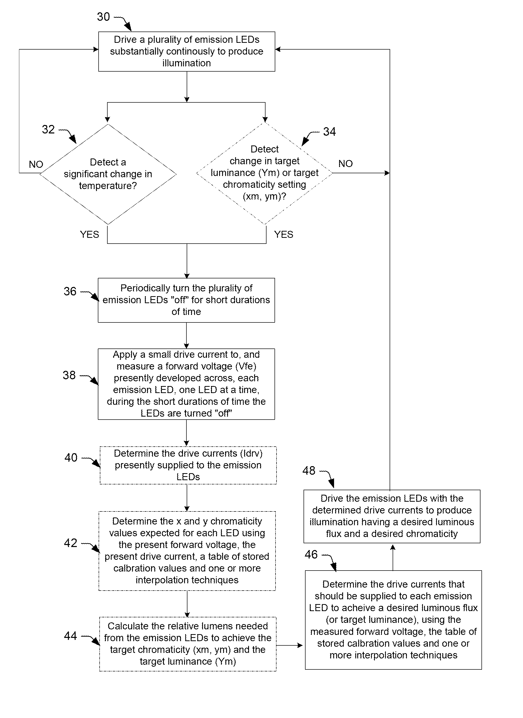
The method described in this patent involves driving LEDs with a continuous drive current to produce illumination, followed by periodic turning off the LEDs for short periods of time to measure the voltage across them. This process is repeated for each LED, allowing for the measurement of voltage levels in each LED. The method may also include using a phase locked loop (PLL) to synchronize the timing of the LED driver and receiver circuit. The technical effect of this patent is improved control and synchronization of LED illumination, which can be useful in various applications such as lighting fixtures or displays.

Problems solved by technology

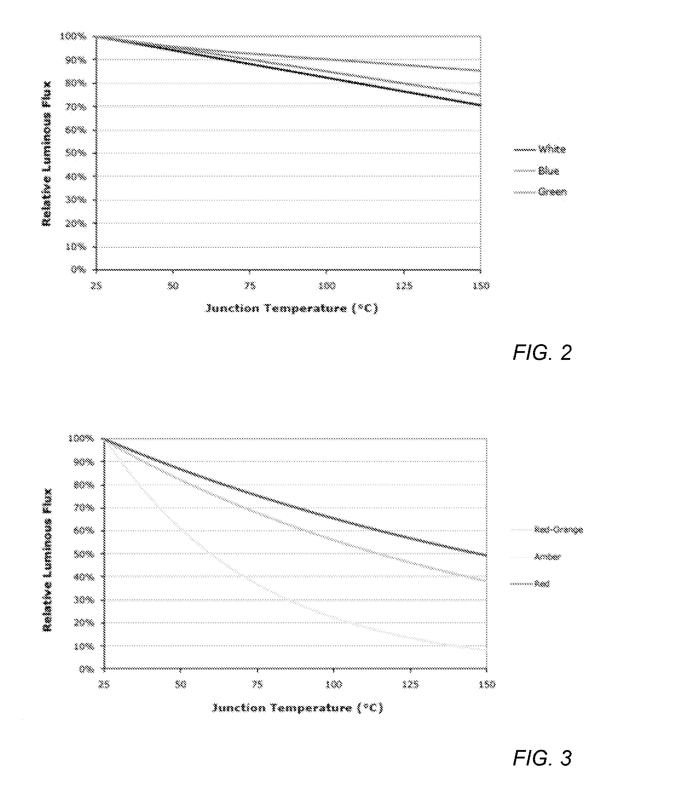
Although LEDs have many advantages over conventional light sources, one disadvantage of LEDs is that their output characteristics (e.g., luminous flux and chromaticity) vary over changes in drive current, temperature and over time as the LEDs age.
Most prior art illumination devices fail to provide an accurate calibration and compensation method for controlling the color of the illumination device.
While prior art devices may perform some level of temperature compensation, they fail to provide accurate results by failing to recognize that temperature affects the lumen output and chromaticity of different colors of LEDs differently.
Moreover, these prior art devices fail to account for chromaticity shifts in the illumination produced by phosphor converted LEDs, which result from phosphor aging.
As a consequence, these prior art devices cannot maintain a desired luminous flux and a desired chromaticity for an LED illumination device over operating conditions and over the lifetime of the illumination device.

Method used


Image

  • Illumination Device and Method for Controlling an Illumination Device over Changes in Drive Current and Temperature
  • Illumination Device and Method for Controlling an Illumination Device over Changes in Drive Current and Temperature
  • Illumination Device and Method for Controlling an Illumination Device over Changes in Drive Current and Temperature

Examples


Embodiment Construction

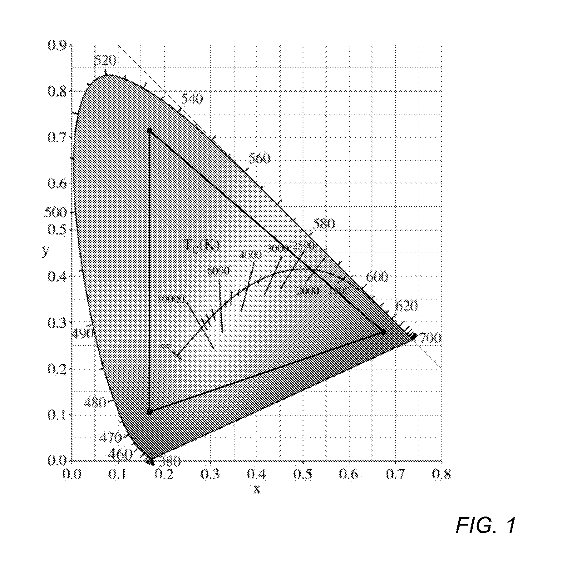
[0074]An LED generally comprises a chip of semiconducting material doped with impurities to create a p-n junction. As in other diodes, current flows easily from the p-side, or anode, to the n-side, or cathode, but not in the reverse direction. Charge-carriers—electrons and holes—flow into the junction from electrodes with different voltages. When an electron meets a hole, it falls into a lower energy level, and releases energy in the form of a photon (i.e., light). The wavelength of the light emitted by the LED, and thus its color, depends on the band gap energy of the materials forming the p-n junction of the LED.

[0075]Red and yellow LEDs are commonly composed of materials (e.g., AlInGaP) having a relatively low band gap energy, and thus produce longer wavelengths of light. For example, most red and yellow LEDs have a peak wavelength in the range of approximately 610-650 nm and approximately 580-600 nm, respectively. On the other hand, green and blue LEDs are commonly composed of m...


PUM


Abstract

An illumination device and method is provided herein for controlling individual light emitting diodes (LEDs) in an LED illumination device, so that a desired luminous flux and a desired chromaticity of the device can be maintained over changes in drive current and temperature. According to one embodiment, the illumination device comprises a plurality of emission LEDs, a storage medium, an LED driver and receiver circuit and a control circuit. The storage medium may store a table of calibration values correlating forward voltage and drive current to chromaticity and luminous flux at a plurality of temperatures for each of the plurality of emission LEDs. The LED driver and receiver circuit may apply respective drive currents to the emission LEDs to produce substantially continuous illumination, and may periodically turn the emission LEDs off to measure operating forward voltages that develop across each emission LED. The control circuit may determine whether a target luminance setting or a target chromaticity setting for the illumination device has changed, and if so, may determine new respective drive currents needed to achieve the target luminance setting and the target chromaticity setting using the operating forward voltages measured across each emission LED, the table of calibration values and one or more interpolation techniques.

Description

RELATED APPLICATIONS[0001]This application is related to commonly assigned U.S. application Ser. Nos. 13 / 970,944, 13 / 970,964, and 13 / 970,990; U.S. Provisional Application No. 61 / 886,471; and U.S. application Ser. No. 14 / 097,339. The entirety of these applications is incorporated herein by reference.BACKGROUND OF THE INVENTION[0002]1. Field of the Invention[0003]This invention relates to illumination devices comprising a plurality of light emitting diodes (LEDs) and, more particularly, to illumination devices and methods for controlling an illumination device, so as to obtain a desired luminous flux and a desired chromaticity of the device over changes in drive current and temperature.[0004]2. Description of the Relevant Art[0005]The following descriptions and examples are provided as background only and are intended to reveal information that is believed to be of possible relevance to the present invention. No admission is necessarily intended, or should be construed, that any of th...

Claims


Application Information

Patent Timeline
Patent Type & Authority Applications(United States)
IPC IPC(8): H05B33/08G01R31/44H05B44/00
CPCH05B33/0866G01R31/44G01R31/2635Y10S362/80H05B37/02H05B33/0845H05B33/0815H05B33/0827H05B33/0857H05B37/0272H05B45/46H05B45/20H05B47/19H05B45/375H05B45/24
Inventor KNAPP, DAVID J.SAVAGE, JOSEPH A.
Owner LUTRON TECH CO LLC
Learn More