Selective laser solidification apparatus and method

a laser solidification and laser solidification technology, applied in the direction of additive manufacturing processes, manufacturing tools, manufacturing data acquisition/processing, etc., can solve the problems of general reduction of material uniformity across the powder layer, affecting the speed at which the hatch line can be written, and affecting the uniformity of the material

Active Publication Date: 2016-01-07
RENISHAW PLC
View PDF15 Cites 72 Cited by
  • Summary
  • Abstract
  • Description
  • Claims
  • Application Information

AI Technical Summary

Benefits of technology

[0018]The apparatus of the present invention may form the plurality of stripes or stripe segment using bidirectional hatch lines. Alternatively, a series of hatch lines may be formed by only moving the laser beam in the same line direction across the stripe or stripe segment. In other words, unidirectional hatch lines may be formed. Preferably, the line direction across the stripe or stripe segment is at least partially opposed to the gas flow direction. In this manner, debris ejected during hatch line formation is carried away from the direction in which the laser beam is advancing across the stripe or stripe segment. Although the improvement associated with using unidirectional hatch lines is relatively small compared to the benefits of aligning the stripe formation direction to the gas flow direction, it does still provide a useful improvement. This is, however, at the expense of significantly reducing the speed at which the hatch lines can be written.
[0019]In one embodiment, the way in which the hatch lines are formed may be varied during use. In particular, the way in which the hatch lines are formed may be selected depending on the orientation of the stripe formation direction relative to the gas flow direction. In other words, the line direction may be selected based on the orientation of the stripe formation direction relative to the gas flow direction. If the angle (α) between the stripe formation direction and the normal

Problems solved by technology

This has been found to produce additional surface roughness and the formation of layers of non-uniform thickness, which additionally create defects (e.g. pores, inclusions etc).
For machines in which the gas flow is uncontrolled, the variation in gas flow direction re

Method used


Image

  • Selective laser solidification apparatus and method
  • Selective laser solidification apparatus and method
  • Selective laser solidification apparatus and method

Examples


Embodiment Construction

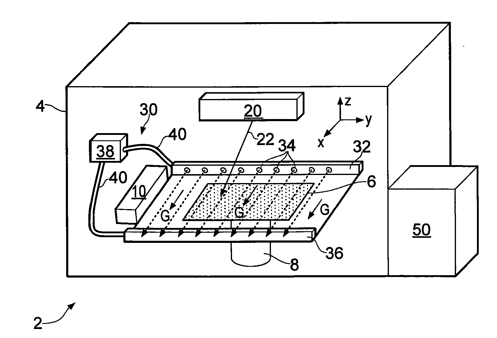
[0041]Referring to FIG. 1, a known selective laser melting machine 2 is schematically illustrated.

[0042]The laser melting machine 2 comprises a build chamber or housing 4 in which there is provided a powder bed 6. The powder bed 6 can be raised and lowed (i.e. moved in the z-direction) by a piston mechanism 8. A powder dispensing and roller system 10 is provided for depositing a thin (e.g. 10-100 μm) powder layer onto the top of the powder bed 6. The powder used to form the powder layer is preferably a metal powder (e.g. 1.2709 grade steel powder).

[0043]A laser scanning unit 20 is also provided that comprises a high power continuous wave (CW) laser and scanning optics to direct a laser beam 22 towards the powder bed 6. The scanning optics also allow the laser beam 22 to be moved rapidly over the surface of the powder bed 6. The laser scanning unit 20 also includes an optical modulator to enable the laser beam 22 that impinges on the powder layer to be turned on and off as required.

[...


PUM

PropertyMeasurementUnit
Angleaaaaaaaaaa
Flow rateaaaaaaaaaa

Abstract

Selective laser solidification apparatus is described that includes a powder bed onto which a powder layer can be deposited and a gas flow unit for passing a flow of gas over the powder bed along a predefined gas flow direction. A laser scanning unit is provided for scanning a laser beam over the powder layer to selectively solidify at least part of the powder layer to form a required pattern. The required pattern is formed from a plurality of stripes or stripe segments that are formed by advancing the laser beam along the stripe or stripe segment in a stripe formation direction. The stripe formation direction is arranged so that it always at least partially opposes the predefined gas flow direction. A corresponding method is also described.

Description

[0001]The present invention relates to selective laser solidification and in particular to an improved selective laser melting process and apparatus in which the direction of laser movement across the powder bed is controlled relative to the direction of gas flow.BACKGROUND[0002]Additive manufacturing or rapid prototyping methods for producing components comprise layer-by-layer solidification of a material, such as a metal powder material, using a laser beam. A powder layer is deposited on a powder bed in a build chamber and a laser beam is scanned across portions of the powder layer that correspond to a cross-section of the component being constructed. The laser beam melts or sinters the powder to form a solidified layer. As explained in more detail below with reference to FIG. 2, it is typical to melt or sinter the desired pattern in the powder layer using a series of stripes. In particular, it is known to advance so-called hatch lines back and forth along a plurality of stripes i...

Claims


Application Information

Patent Timeline
IPC IPC(8): B23K26/142B23K26/08B23K26/342
CPCB23K26/142B23K26/342B23K26/0869B28B1/001B29C64/153B33Y30/00B33Y50/02B33Y10/00B22F2999/00B29C64/393Y02P10/25B22F12/70B22F12/49B22F12/63B22F10/366B22F10/28B22F10/322B22F10/36B22F12/41B22F2202/11B22F2201/02B22F2201/10B23K26/1438B23K26/1437B22F10/10B22F12/00B22F10/30
Inventor DIMTER, MARC FRANKMAYER, RALPH MARKUSHESS, THOMAS
Owner RENISHAW PLC
Why Eureka
Try Eureka