Shift position switching device

a technology of shifting position and switching controller, which is applied in the direction of mechanical equipment, instruments, transportation and packaging, etc., can solve the problems of long reference position, unsatisfactory product life and durability of the motor, and inability to save the power consumption of the motor, etc., and achieve the effect of durable consciousness

Active Publication Date: 2016-01-07
DENSO CORP
View PDF2 Cites 56 Cited by
  • Summary
  • Abstract
  • Description
  • Claims
  • Application Information

AI Technical Summary

Benefits of technology

[0009]In such manner, the shift mechanism is appropriately controlled based on the reference position of the motor on the first shift position side, where the position is learned as des

Problems solved by technology

However, the method in the above-mentioned patent document 1 forces the motor to rotate for a certain period of time at the dead-end rotation position, thereby forcing the motor and the switching mechanism to warp and twist when learning the reference position, which may be undesirable in terms of the product life and durability of the motor.
In addition, the learning time for learning

Method used


Image

  • Shift position switching device
  • Shift position switching device
  • Shift position switching device

Examples


Embodiment Construction

[0023]Embodiments of the present disclosure are hereinafter described in connection with the drawings. In the following description, like components are denoted by like reference characters, and the like components are named identically and function identically. Thus, a detailed description thereof will not be repeated. Further, it is noted that the terms “shift range” and “shift position” are herein used interchangeably.

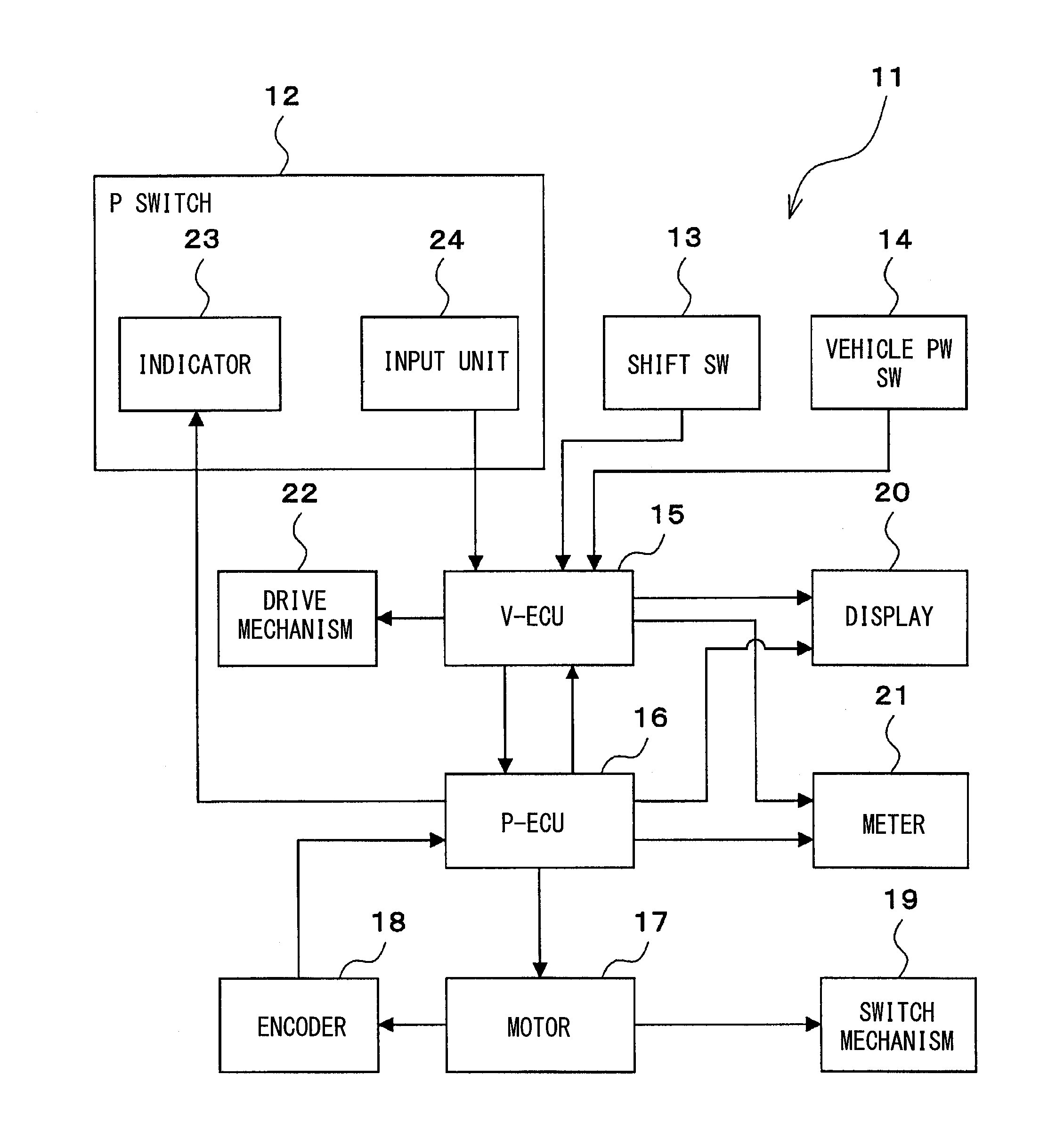
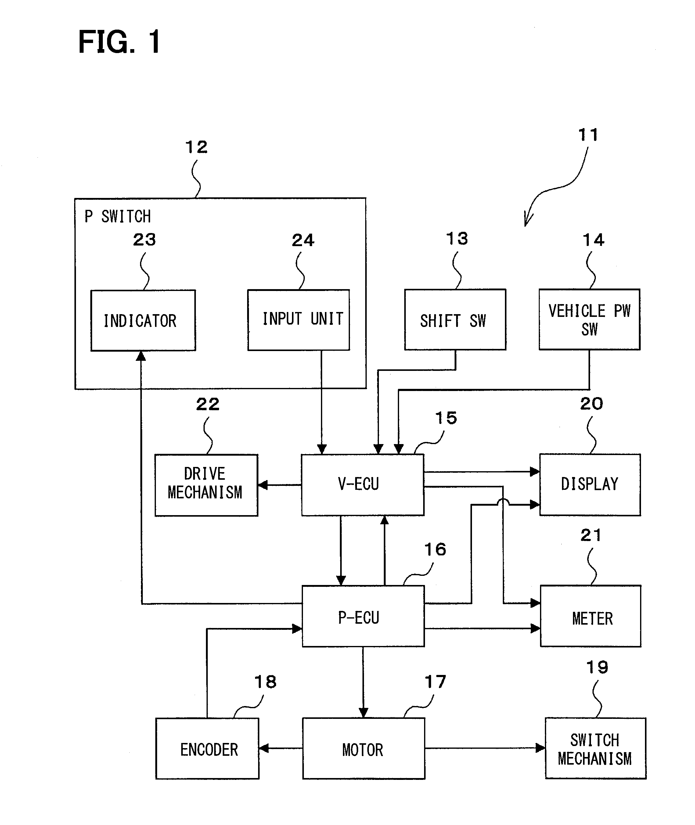
[0024]FIG. 1 shows a configuration of a shift control system 11 according to one embodiment of the present disclosure. The shift control system 11 of the present embodiment is used for switching the shift range of a vehicle. The shift control system 11 includes a P switch 12, a shift switch 13, a vehicle power switch 14, a vehicle control unit (hereinafter referred to as “V-ECU”) 15, a parking control unit (hereinafter “P-ECU”) 16, a motor 17, an encoder 18, a shift mechanism 19, a display unit 20, a meter 21, and a drive mechanism 22 together with other parts. The ...


PUM


Abstract

A shift position switching device for shifting gears in association with a shift position. The device includes a shift mechanism switching between shift positions using a drive power of a motor, an encoder outputting pulse signals in sync with a rotation of the motor, and a controller rotating the motor to a target rotation position corresponding to an intended gear. The controller rotates the motor toward a dead-end on a first shift position side of the shift mechanism while observing a motor rotation speed or an acceleration of rotation of the motor based on the outputted pulse signals of the encoder. Also, the controller learns, as a reference position on the first shift position side, a first rotation position of the motor.

Description

CROSS REFERENCE TO RELATED APPLICATION[0001]The present application is based on and claims the benefit of priority of Japanese Patent Application No. 2014-137203, filed on Jul. 2, 2014, the disclosure of which is incorporated herein by reference.TECHNICAL FIELD[0002]The present disclosure generally relates to a shift position switching controller for switching between shift positions by using a motor as its power source.BACKGROUND INFORMATION[0003]Mechanical drive systems in vehicles are gradually replaced with electrical drive—by-wire—systems, for space efficiency, assemblability, controllability and the like, where the mechanism of the drive system is driven by motors. An example of such a replacement is found in the field of mechanical transmission, for example, in a shift position switching mechanism driven by a motor. In such a system, the drive control of the motor is performed based on an encoder count, or counting the number of pulse signals from the encoder installed in the...

Claims


Application Information

Patent Timeline
IPC IPC(8): F16H61/02B60K23/02F16H59/08
CPCF16H61/0204F16H59/08B60Y2300/70B60K2702/02B60K23/02F16H59/105F16H61/32F16H2061/0087F16H2061/326
Inventor KIMURA, KIYOSHIYAMADA, JUN
Owner DENSO CORP
Why Eureka
Try Eureka