Working machine feed axis control method and feed axis control device

Active Publication Date: 2016-01-07
MAKINO MILLING MASCH CO LTD
View PDF16 Cites 10 Cited by
  • Summary
  • Abstract
  • Description
  • Claims
  • Application Information

AI Technical Summary

Benefits of technology

[0008]With the present invention, the torque command from which the state feedback signal, obtained by multiplying the output of the feedback loop by the gain, has been subtracted is outputt

Problems solved by technology

However, some types of disturbances acting on the feed axis are unpredictable.
Therefore, the method in which the predicted processing load is calcu

Method used


Image

  • Working machine feed axis control method and feed axis control device
  • Working machine feed axis control method and feed axis control device
  • Working machine feed axis control method and feed axis control device

Examples


Embodiment Construction

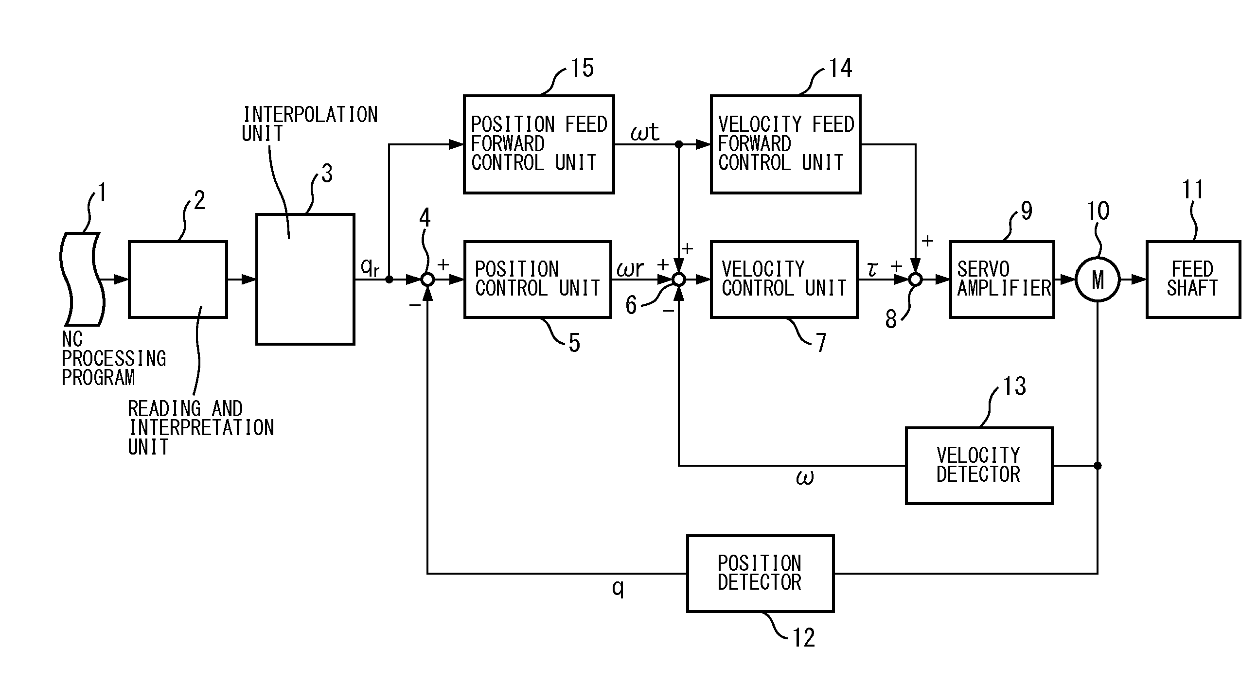
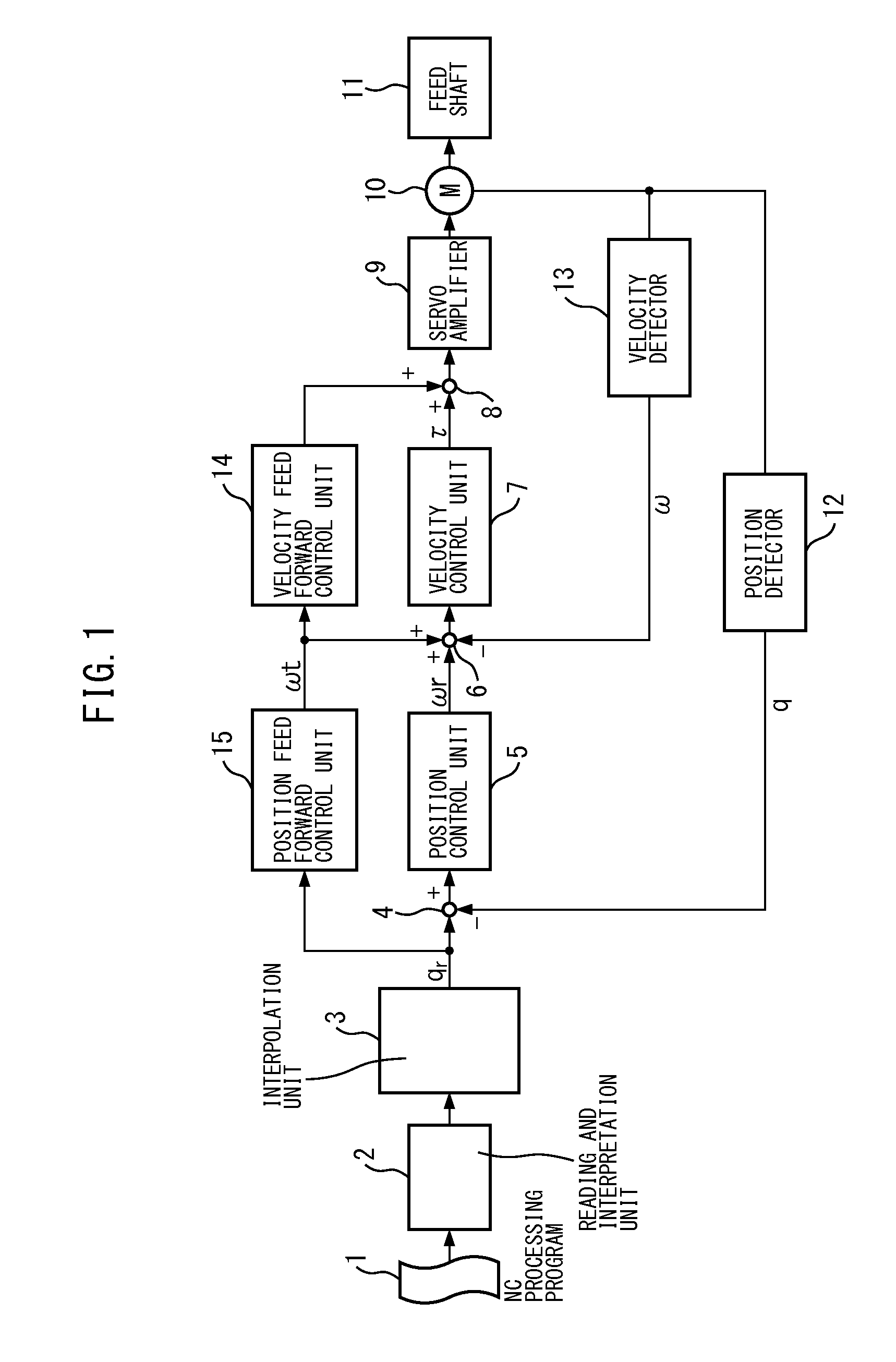
[0019]Hereafter, an embodiment of a machine tool feed axis control device according to the present invention will be described, with reference to FIG. 1 to FIG. 10. FIG. 1 is a block diagram representing a hardware configuration of the machine tool feed axis control device according to the embodiment of the present invention. The machine tool may be exemplified by NC machine tool such as a machining center including a feed axis driven by a servo motor, and the feed axis control device constitutes a part of the numerical control device.

[0020]As illustrated in FIG. 1, an NC processing program 1 installed in the numerical control device is inputted in an interpolation unit 3 through a reading and interpretation unit 2. The interpolation unit 3 outputs a position command qr for the driving servo motor of each of the feed axis (e.g., an X-direction axis). The position command qr (rotational position command of the motor) outputted from the interpolation unit 3 is inputted to a position c...


PUM


Abstract

A working machine feed axis control device: disposes a velocity feedback loop and forms a cascade coupling on the inner side of a location feedback loop; comprises a velocity gain setting apparatus (30) which multiplies the output of the velocity feedback look by a first gain (kv), and a location gain setting apparatus (31) which multiplies the output of the location feedback loop by a second gain (kp); subtracts the output of the velocity gain setting apparatus (30) and the output of the location gain setting apparatus (31) from a torque instruction (τ); and outputs the remaining torque instruction (τ) to a subject to be controlled (27).

Description

CROSS-REFERENCE TO RELATED APPLICATIONS[0001]This application is a U.S. National Phase patent application of International Patent Application No. PCT / JP2014 / 055130, filed on Feb. 28, 2014, which claims the priority of Japanese Application No. 2013-045163 filed Mar. 7, 2013, which is hereby incorporated by reference in the present disclosure in its entirety.FIELD OF THE INVENTION[0002]The present invention relates to a feed axis control method and feed axis control of a machine tool, which control a servo motor for driving the feed axis of a machine tool by means of a control circuit having a position feedback loop and a velocity feedback loop.BACKGROUND OF THE INVENTION[0003]A method of controlling a servo motor for driving a feed axis through a control circuit in which cascade-connection is formed by providing a velocity feedback loop inside the position feedback loop, has thus far been known (for example, as disclosed in Patent Literature 1). The method according to PTL 1 includes...

Claims


Application Information

Patent Timeline
IPC IPC(8): G05B19/416
CPCG05B2219/32276G05B19/4166G05B19/19G05B2219/42063
Inventor ODA, MITSUNARI
Owner MAKINO MILLING MASCH CO LTD
Why Eureka
Try Eureka