

Battery module
- Summary
- Abstract
- Description
- Claims
- Application Information
AI Technical Summary
Benefits of technology
Problems solved by technology
Method used
Image

Examples
first exemplary embodiment
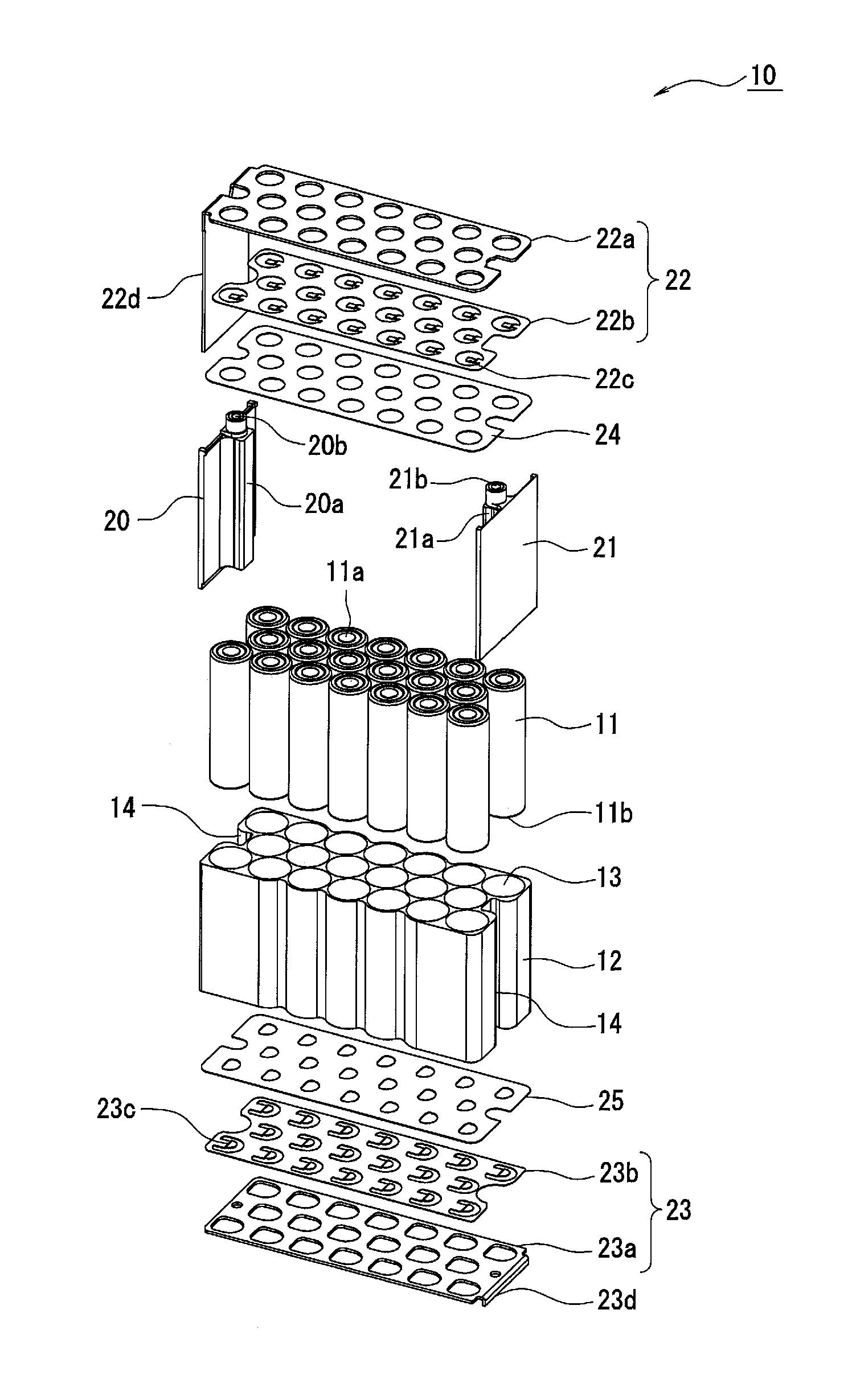
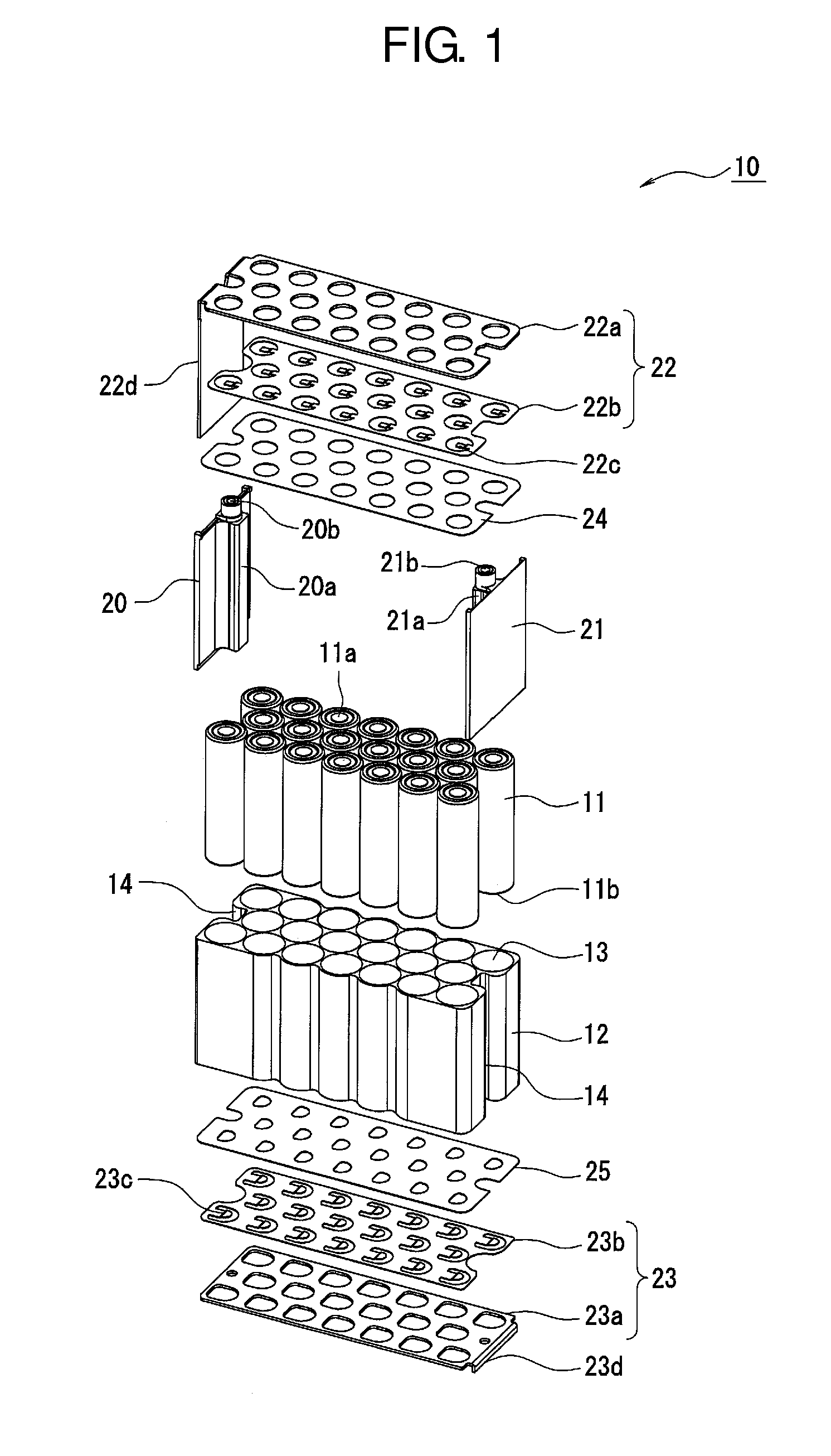
[0025]Each of FIG. 1 through FIG. 3 shows battery module 10 of the first exemplary embodiment.
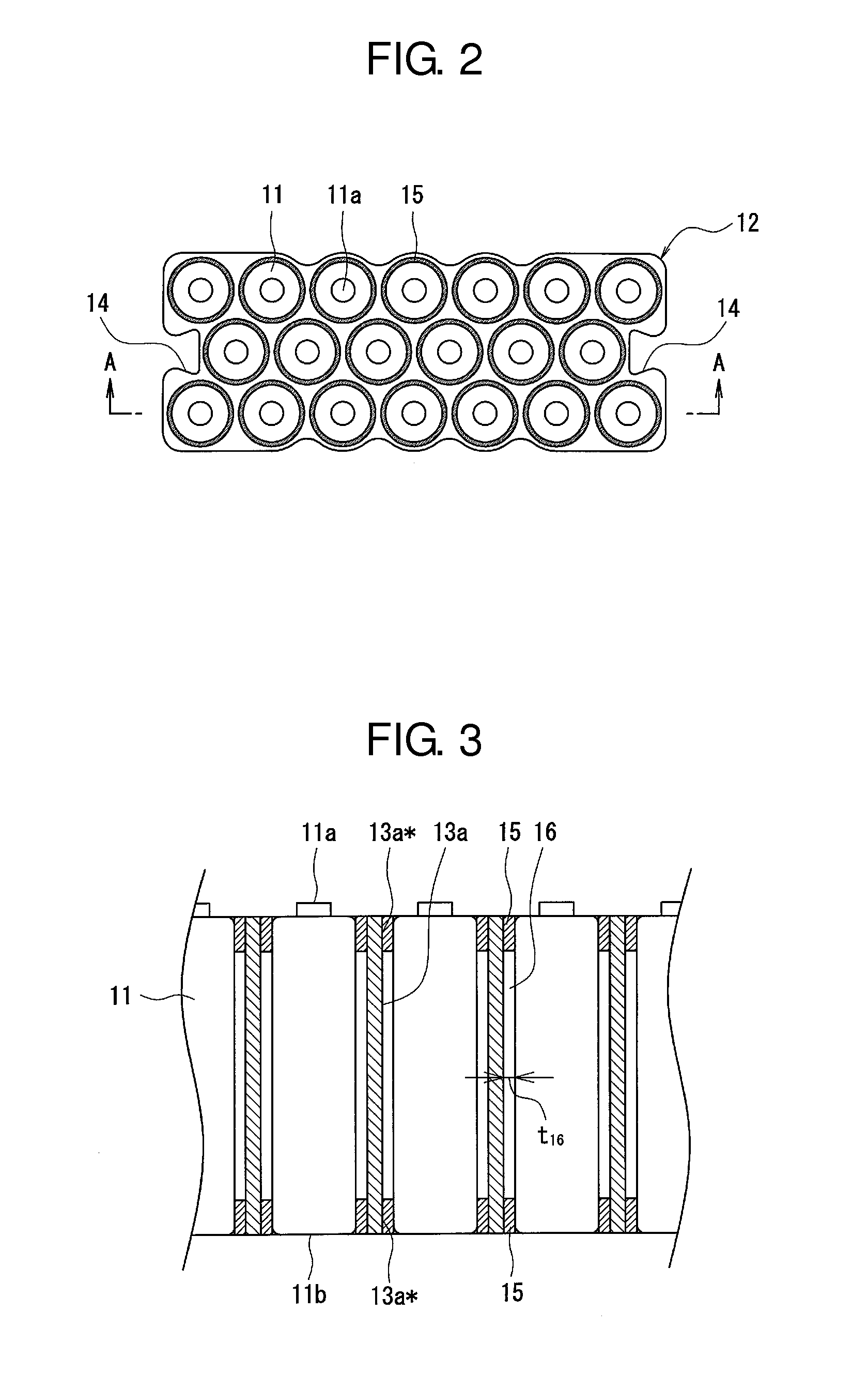
[0026]FIG. 1 is an exploded perspective view showing an overall configuration of battery module 10. FIG. 2 is a top view showing battery case 12 that holds batteries 11. FIG. 3 is a diagram showing part of a section of battery case 12 taken along the axial direction of battery 11 (a section taken along AA line of FIG. 2).
[0027]Battery module 10 includes a plurality of batteries 11 and battery case 12 that holds individual batteries 11. Battery case 12 has a block shape having a plurality of through-holes passing through the case in the vertical direction, and the through-holes form a plurality of holding parts 13 holding corresponding batteries 11. In this exemplary embodiment, battery case 12 has a substantially rectangular shape as viewed from the top and is long in the length direction. Battery case 12 has 20 independent holding parts 13, but the number of holding parts 13 is not limited...
second exemplary embodiment
[0050]Each of FIG. 6 and FIG. 7 shows battery module 30 in accordance with the second exemplary embodiment. FIG. 6 is a perspective view of battery case 31 that holds batteries 11. FIG. 7 is a drawing showing part of a section taken along BB line of FIG. 6. In the following description, elements common to those of the first exemplary embodiment have the same reference marks, the description of the elements is omitted, and differences from the first exemplary embodiment are detailed.
[0051]Battery module 30 differs from that of the first exemplary embodiment in that the battery module includes battery case 31 instead of battery case 12. Battery case 31 is configured by combining a plurality of metallic pipes 32. For instance, plurality of metallic pipes 32 is welded to each other and forms one battery case 31. Similarly to battery module 10, battery module 30 includes connecting members and insulating members for positive and negative electrodes. However, because battery case 31 is us...
third exemplary embodiment
[0066]FIG. 10 shows battery module 40 in accordance with the third exemplary embodiment.
[0067]FIG. 10 is a sectional view of battery module 40 taken along the axial direction of battery 11, and corresponds to each of FIG. 3 and FIG. 7.
[0068]Battery module 40 differs from that of the first exemplary embodiment in that the battery module includes battery case 41 instead of battery case 12. In battery case 41, the length of holding part 42 (longitudinal length) is shorter than the axial length of battery 11. Thus, battery 11 protrudes from holding part 42 at both ends of holding part 42. Because of such a difference, each of insulating members 43, 44 has projections for surrounding the portions where corresponding batteries protrude from holding parts 42. In other words, each of insulating members 43, 44 has a plurality of recesses capable of receiving axial ends of corresponding batteries 11. In this exemplary embodiment, each of insulating member 43, 44 functions as a holding member ...
PUM
 Abstract
Description
Claims
Application Information