
Apparatus and method for state of charge compensation of an energy storage system

Inactive Publication Date: 2016-01-07
ROLLS ROYCE DEUT LTD & CO KG
View PDF3 Cites 16 Cited by
  • Summary
  • Abstract
  • Description
  • Claims
  • Application Information

AI Technical Summary

Benefits of technology

The present invention is a control device for a battery system that can operate in different modes and with different energy storage modules. The control device monitors, controls, and synchronizes the power flows between the sub modules and the electrical machine or winding. The design allows for flexible and efficient operation of the battery system, with different battery modules being used based on their characteristics. The control device can also control the amount of energy drawn from each module, optimizing power flow and ageing behavior. The overall system is designed to be more reliable, flexible, and efficient.

Problems solved by technology

This is not the case with today's systems in which the calls are connected in series, as the entire system becomes inoperable if a cell fails.

Method used


Image

  • Apparatus and method for state of charge compensation of an energy storage system
  • Apparatus and method for state of charge compensation of an energy storage system
  • Apparatus and method for state of charge compensation of an energy storage system

Examples


Embodiment Construction

[0027]Throughout all the figures, same or corresponding elements may generally be indicated by same reference numerals. These depicted embodiments are to be understood as illustrative of the invention and not as limiting in any way. It should also be understood that the figures are not necessarily to scale and that the embodiments are sometimes illustrated by graphic symbols, phantom lines, diagrammatic representations and fragmentary views. In certain instances, details which are not necessary for an understanding of the present invention or which render other details difficult to perceive may have been omitted.

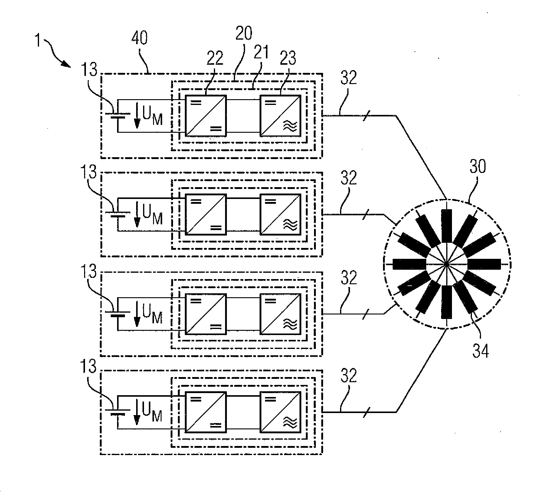
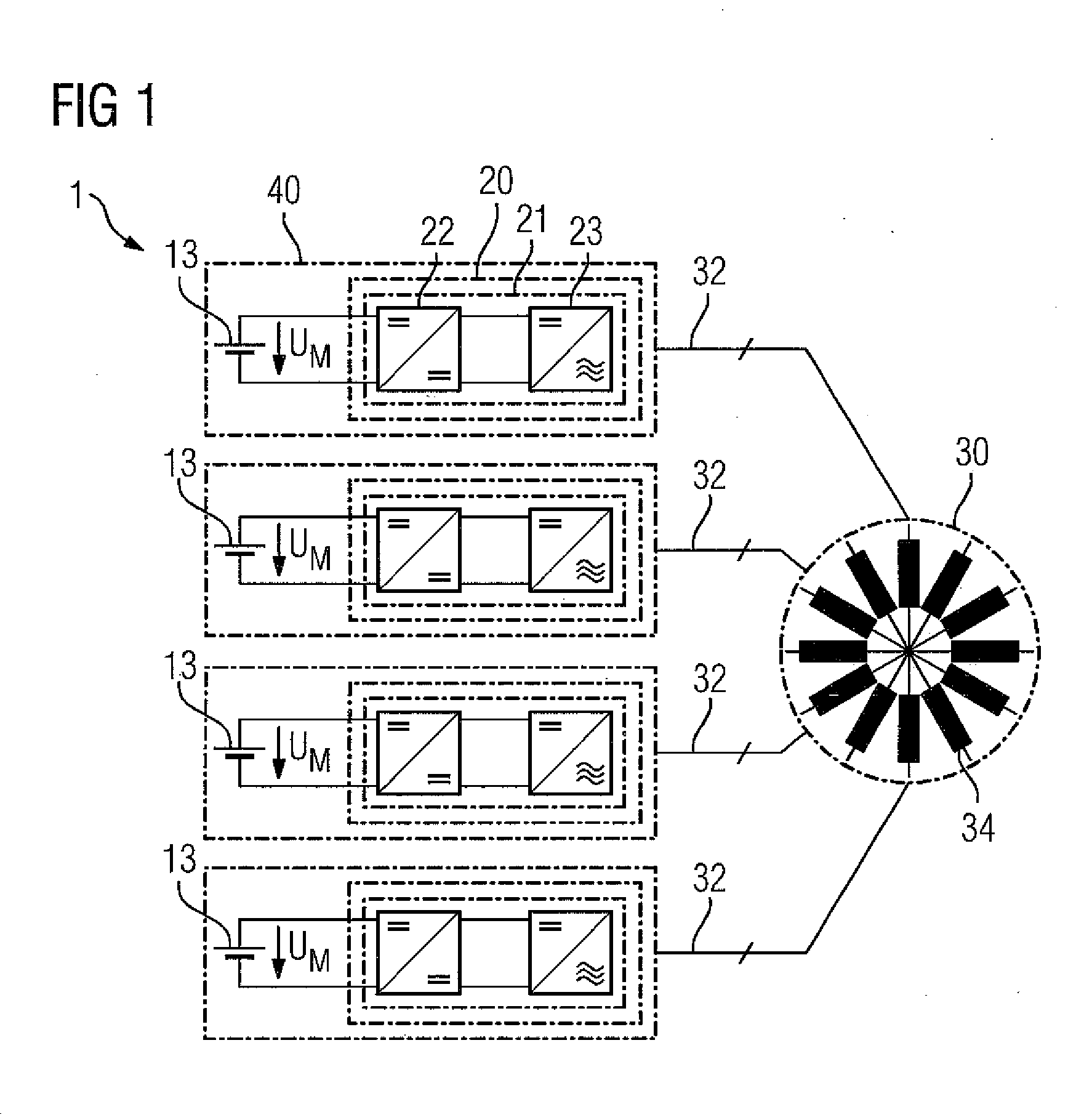
[0028]Turning now to the drawing, and in particular to FIG. 1, there is shown an apparatus 1 for state of charge compensation. The apparatus 1 has four submodules 40. Each of the submodules 40 includes an energy storage module 13 across which an energy storage module voltage UM is dropped. The energy storage module voltage UM is fed to a voltage converter module 20. The volt...


PUM


Abstract

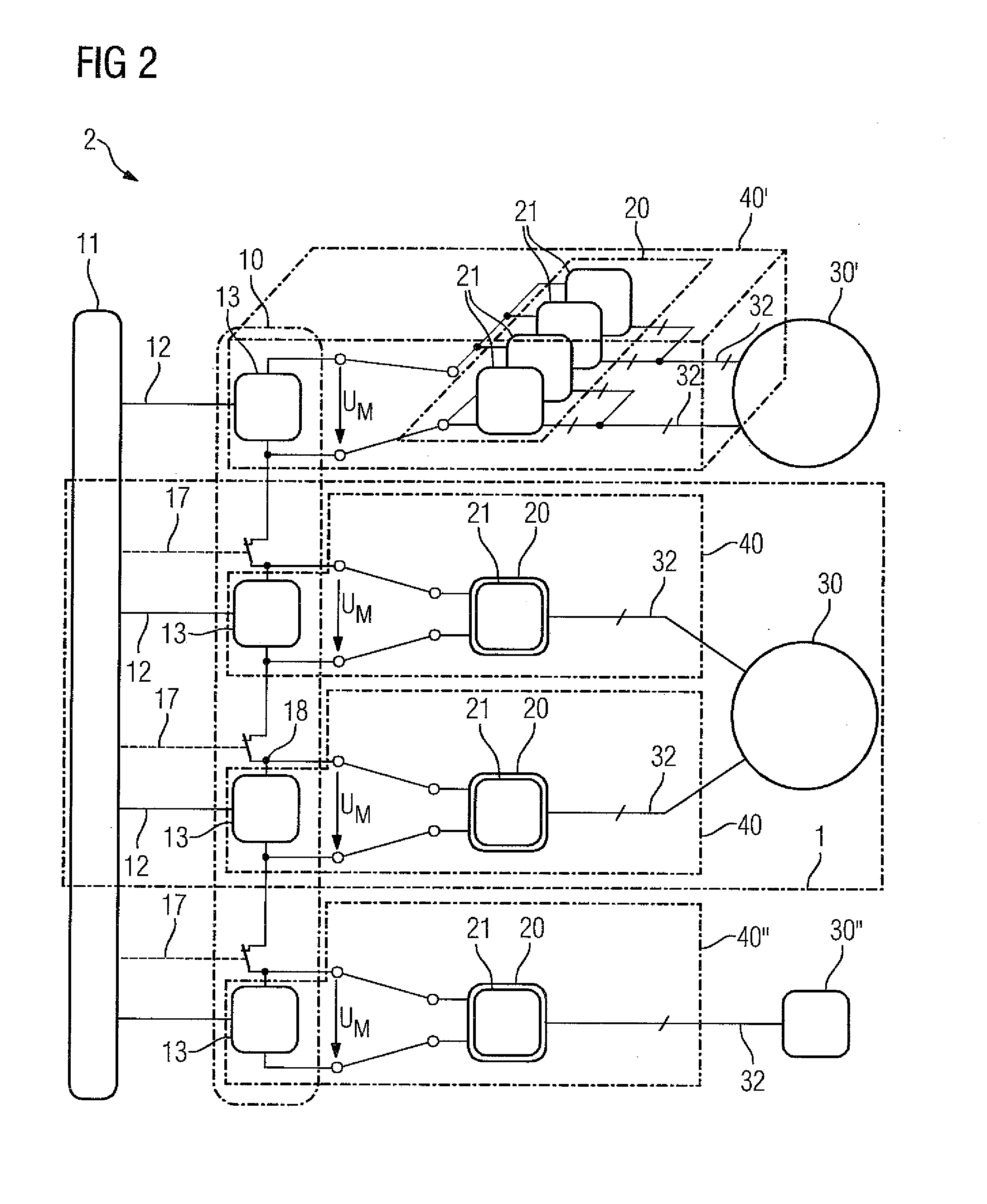
An apparatus for state of charge compensation includes at least two energy storage modules, each energy storage module having an energy storage module voltage, at least two voltage converter modules, with each voltage converter module being electrically connected to a respective one of the at least two energy storage modules in one-to-one correspondence and forming a corresponding submodule, an electrical machine electrically connected to the at least two submodules, and a control device configured to control a flow of electrical energy between at least one of the submodules and the electrical machine.

Description

CROSS-REFERENCES TO RELATED APPLICATIONS[0001]This application claims the priority of German Patent Application, Serial No. 10 2014 212 934.6, filed Jul. 3, 2014, pursuant to 35 U.S.C. 119(a)-(d), the content of which is incorporated herein by reference in its entirety as if fully set forth herein.BACKGROUND OF THE INVENTION[0002]The present invention relates to an apparatus for state of charge compensation and to a method for state of charge compensation.[0003]The following discussion of related art is provided to assist the reader in understanding the advantages of the invention, and is not to be construed as an admission that this related art is prior art to this invention.[0004]To supply power to electrical components, electrical energy / power storage devices are generally provided. Such energy / power storage devices can be, for example, battery cells which provide a battery cell voltage, or capacitors. In order to provide a desired voltage level, the battery cells are normally in...

Claims


Application Information

Patent Timeline
IPC IPC(8): H02J7/00H02J1/16
CPCH02J1/16H02J7/0014B60L50/51B60L58/22Y02T10/70Y02E60/10H01M10/441
Inventor MIKULEC, DRAGANWERNER, TIMURWEYDANZ, WOLFGANG
Owner ROLLS ROYCE DEUT LTD & CO KG
Features
  • Generate Ideas
  • Intellectual Property
  • Life Sciences
  • Materials
  • Tech Scout
  • Unparalleled Data Quality
  • Higher Quality Content
  • 60% Fewer Hallucinations
Learn More