Electroacoustic conversion film, electroacoustic converter, flexible display, and projector screen

a technology of electroacoustic converter and conversion film, which is applied in the direction of mechanical vibration separation, generator/motor, instruments, etc., can solve the problems of increased thickness of display, impaired display characteristic, and difficulty in integrating vibration plates with flexible displays. achieve the effect of breaking a frequency band

Active Publication Date: 2016-01-14
FUJIFILM CORP
View PDF4 Cites 25 Cited by
  • Summary
  • Abstract
  • Description
  • Claims
  • Application Information

AI Technical Summary

Benefits of technology

[0010]The present invention has been made to solve the above-described problems in the conventional art, and an object of the present invention is to provide an electroacoustic conversion film capable of reproducing a plurality of diffe

Problems solved by technology

However, as described in JP 2003-244791 A, if the vibration plate is divided into a plurality of regions, and the curved portion is formed using the respective regions, there is a problem in that it is difficult for the vibration plate to be integrated with a flexible display.
Further, when the vibration plate is integrated with a thin display, it is necessary for the di

Method used


Image

  • Electroacoustic conversion film, electroacoustic converter, flexible display, and projector screen
  • Electroacoustic conversion film, electroacoustic converter, flexible display, and projector screen
  • Electroacoustic conversion film, electroacoustic converter, flexible display, and projector screen

Examples


example 1

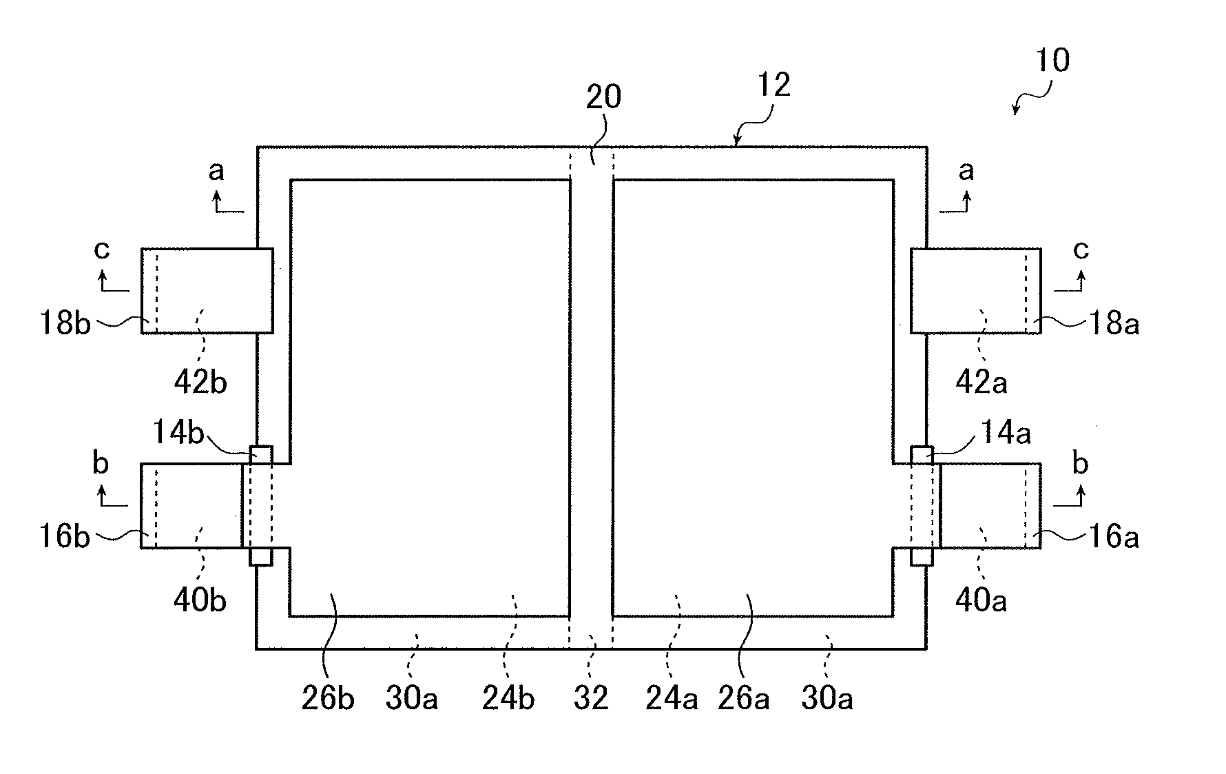
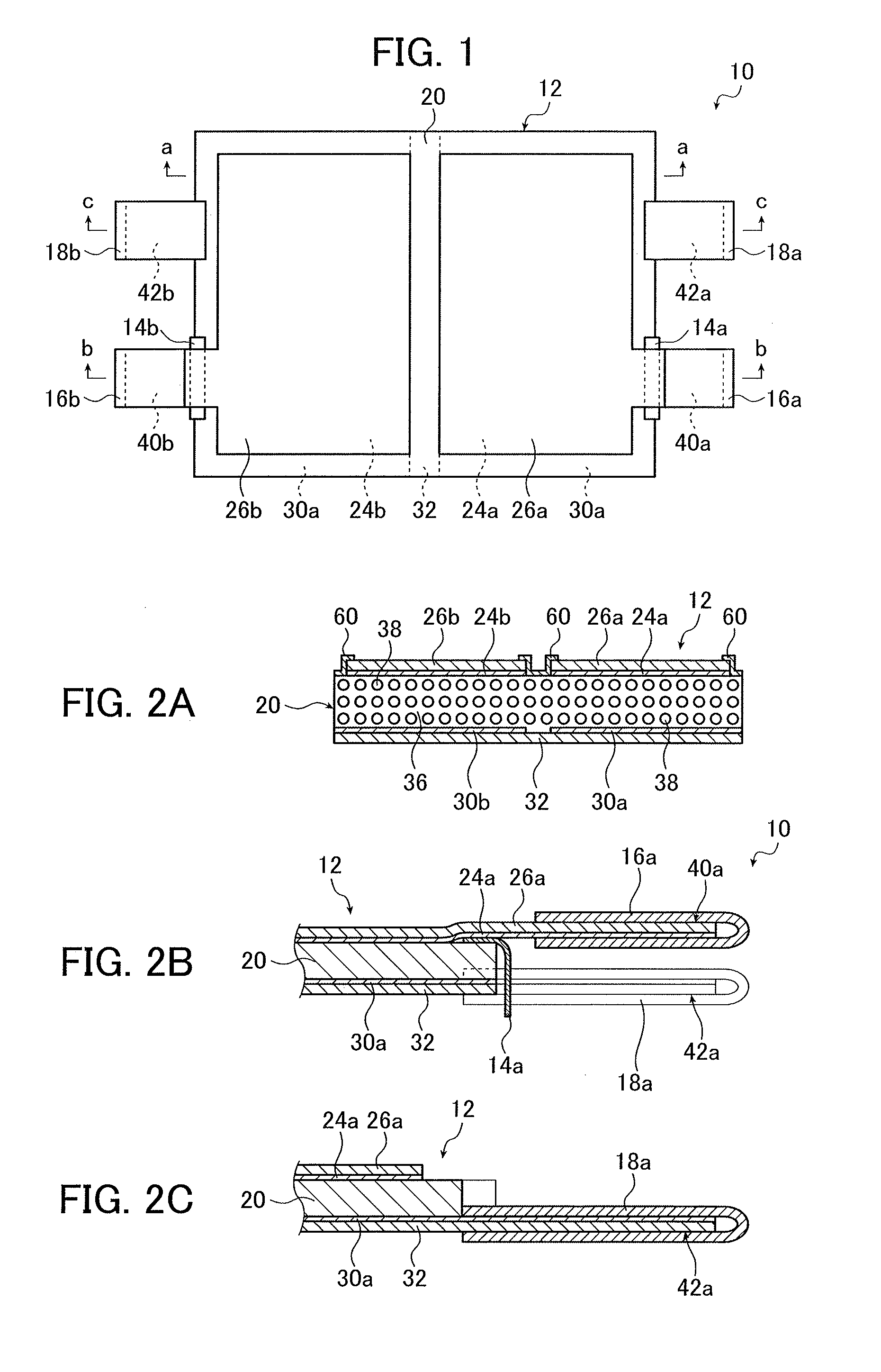
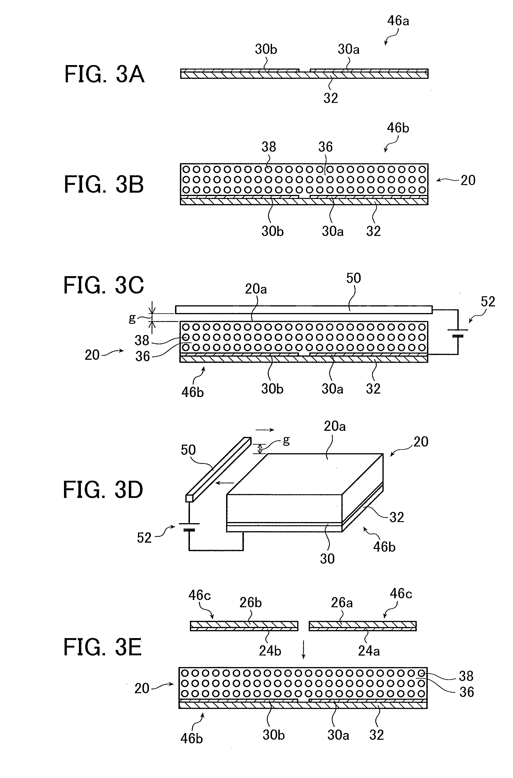
[0315]By the method described above in FIGS. 3A to 3E and FIGS. 4A to 4C, the conversion film 10 of the present invention shown in FIG. 1 was prepared.

[0316]First, in the following compositional ratio, cyanoethylated PVA (CR-V manufactured by Shin-Etsu Chemical Co., Ltd.) was dissolved in dimethylformamide (DMF). Thereafter, PZT particles were added to this solution in the following compositional ratio and dispersed by a propeller mixer (rotation frequency of 2,000 rpm), thereby preparing a coating material for forming the piezoelectric body layer 20.

PZT particles300 parts by mass Cyanoethylated PVA30 parts by massDMF70 parts by mass

[0317]The PZT particles used were prepared by sintering commercially available PZT raw material powder at 1,000° C. to 1,200° C. and then performing pulverization and classification treatment on the resultant so as to obtain the particles having an average particle size of 5 μm.

[0318]Meanwhile, sheet-like materials 46a and 46c were prepared by vacuum-dep...

example 2

[0338]Next, the conversion film 300 illustrated in FIG. 18 was manufactured in Example 2.

[0339]In Example 2, the conversion film 300 was prepared in the same manner as in Example 1, except that the size of the vibration surface was 220 mm×330 mm, the size of the first upper electrode 24a was 200 mm×200 mm, the size of the second upper electrode 24b was 200 mm×100 mm, the width of the separation region between the first upper electrode 24a and the second upper electrode 24b was 10 mm, the width of the margin around the upper electrode was 10 mm, and the common electrode 330 covering the entire vibration surface was used in place of the lower electrodes 30a and 30b.

[0340]As in Example 1, the conversion film 300 prepared as above was incorporated into the case 82 to prepare a speaker. Using a constant current type power amplifier, a sine wave at 1 kHz was input to the electrode pair (first active region) of the first upper electrode 24a and the common electrode 330, and a sine wave at...

reference example 1

[0343]A conversion film was prepared in the same manner as in Example 2, except that one upper electrode of 200 mm×300 mm was used and the conversion film had one electrode pair. As in Example 2, the prepared conversion film is incorporated into the case 82 to prepare a speaker. Using the prepared speaker, the sound pressure level-frequency characteristics measurement was performed with respect to a case in which a sine wave at 1 kHz was input to the electrode pair, and a case in which a sine wave at 1.25 kHz was input to the electrode pair. The measurement result is illustrated in FIG. 24A.

[0344]In Reference Example 1, the sound pressure level-frequency characteristics measurement was performed when the sine wave at 1 kHz and the sine wave at 1.25 kHz were simultaneously input to the electrode pairs. The measurement result is illustrated in FIG. 24B.

[0345]It can be seen from FIGS. 24A and 24B that when signals at different frequencies are simultaneously input to the conversion film...


PUM


Abstract

The present invention provides an electroacoustic conversion film comprising: a polymeric composite piezoelectric body in which piezoelectric body particles are dispersed in a viscoelastic matrix formed of a polymer material exhibiting viscoelasticity at normal temperature; and two or more electrode pairs, wherein one electrode and the other electrode of each of the electrode pairs are arranged on two opposite main surfaces of the polymeric composite piezoelectric body, respectively, to interpose the polymeric composite piezoelectric body therebetween, and thereby each of the electrode pairs forms an active region.

Description

CROSS-REFERENCE TO RELATED APPLICATIONS[0001]This application is a Continuation of PCT International Application No. PCT / JP2014 / 058567 filed on Mar. 26, 2014, which claims priority under 35 U.S.C. §119(a) to Japanese Patent Application No. 2013-068354 filed on Mar. 28, 2013 and Japanese Patent Application No. 2013-218401 filed on Oct. 21, 2013. Each of the above application(s) is hereby expressly incorporated by reference, in its entirety, into the present application.BACKGROUND OF THE INVENTION[0002]The present invention relates to an electroacoustic conversion film used for an acoustic device such as a speaker, and to an electroacoustic converter, a flexible display, and a projector screen using the electroacoustic conversion film.[0003]In a flexible display using a flexible substrate (for example, plastics) such as an organic EL display, it has been considered that a flexible piezoelectric film having a sheet shape is adopted as a speaker that can be integrated with a flexible di...

Claims


Application Information

Patent Timeline
IPC IPC(8): B06B1/06G03B21/56G10K11/178H04R17/02
CPCB06B1/0662G03B21/56H04R17/025G10K2210/3229H04R2499/15H04R2307/025G10K11/1788H04R5/02H04R7/04H04R17/005B06B1/0688H04R2217/03G03B31/00G10K11/17857G10K11/1787G10K11/1785H10N30/87H10N30/875H10N30/852H10N30/092H10N30/2047H10N30/045
Inventor MIYOSHI, TETSU
Owner FUJIFILM CORP
Why Eureka
Try Eureka