Stable Low Aspect Ratio Flying Wing

Inactive Publication Date: 2016-01-14
FRIESEL ERIC WALTER
View PDF19 Cites 19 Cited by
  • Summary
  • Abstract
  • Description
  • Claims
  • Application Information

AI Technical Summary

Benefits of technology

[0026]Present disclosures reference a low aspect ratio flying wing that provides stability throughout the flight envelope from stall to maximum speed. This provides a stable low aspect ratio flying wing aircraft for all uses. A main structure of a low aspect ratio wing provides increased wing area yielding better than predicted advantage for improved lift generation using multiple design features. Unique tail configuration provides excellent stability at high and low angles of attack by minimizing effect of unpredictable aft end airflow characteristic of low aspect ratio wings. Further, this tail configuration provides significantly improved aerodynamic efficiency over other tail configurations. Novel use of suction and blowing slots on the present invention dramatically improves aerodynamic efficiency and coefficient of lift based on the large airfoil area and short wingspan with better than predicted results. Asymmetrically varying air pressure supplied to one or more suction and blowing slots provides aerodynamic optimization and control of yaw, pitch and roll independent of moveable surfaces. Application of suction and blowing slots specifically to wings of low aspect ratio is not found in “prior art” and is novel and non-obvious in that it provides better than predicted improvement in aerodynamic efficiency and control with lower implementation weight and structural complexity. Lateral extension and retraction of the wing improves aerodynamic efficiency and performance in multiple operational regimes. Combining these features creates a stable low aspect ratio flying wing at reduced cost and with improved aerodynamic ef

Problems solved by technology

Combining low aspect ratio with the already complex flying wing design presents additional challenges forming significant subsections of the flying wing design “prior art” effort dating back to at least 1931.
Two primary challenges of low aspect ratio flying wing designs are aerodynamic stability and aerodynamic efficiency.
The first challenge of flying wing stability has been effectively overcome in “prior art” with complex and costly active computerized dynamic flight controls.
Static control designs in low aspect ratio “prior art” without expensive active systems have been largely abandoned due to unpredictable and sometimes dangerous instability documented in recurring NASA lifting body research and other NASA reports (i.e. NPL 2).
Current state-of-the-art flying wing designs in use rely on expensive active controls that are justified to achieve other performance objectives in very specialized applications.
In addition to stability problems, low aspect ratio designs, with short wingspan relative to chord length, have a reduced aerodynamic efficiency.
As aircraft aerodynamic efficiency decreases fuel efficiency decreases yielding increased life-cycle costs for operation.
Understanding ae

Method used


Image

  • Stable Low Aspect Ratio Flying Wing
  • Stable Low Aspect Ratio Flying Wing
  • Stable Low Aspect Ratio Flying Wing

Examples


example 1

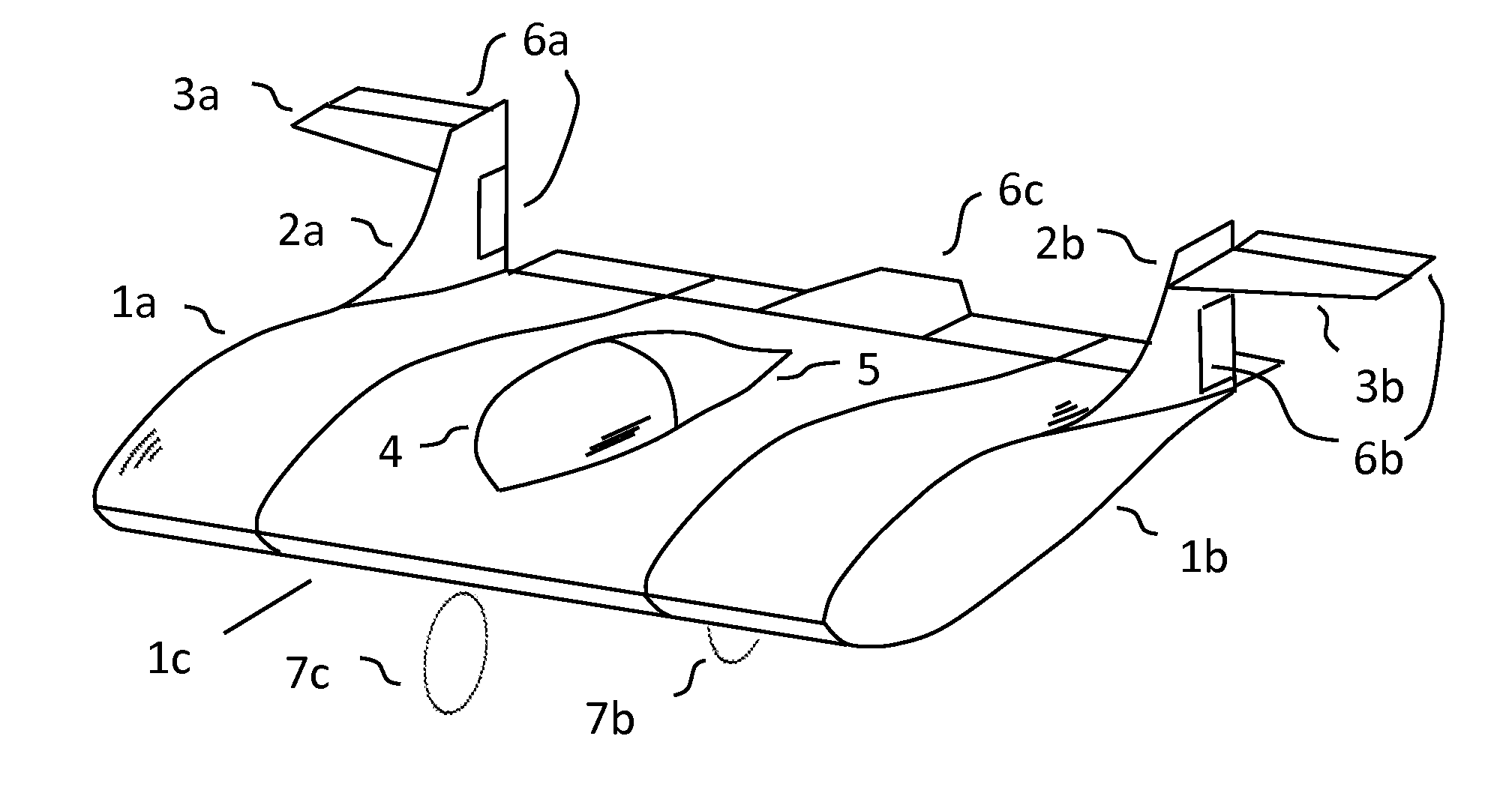
[0051]A first embodiment example is a low aspect ratio flying wing leveraging aspects of disclosures without dihedral, without wing sweep, and without boundary layer control.

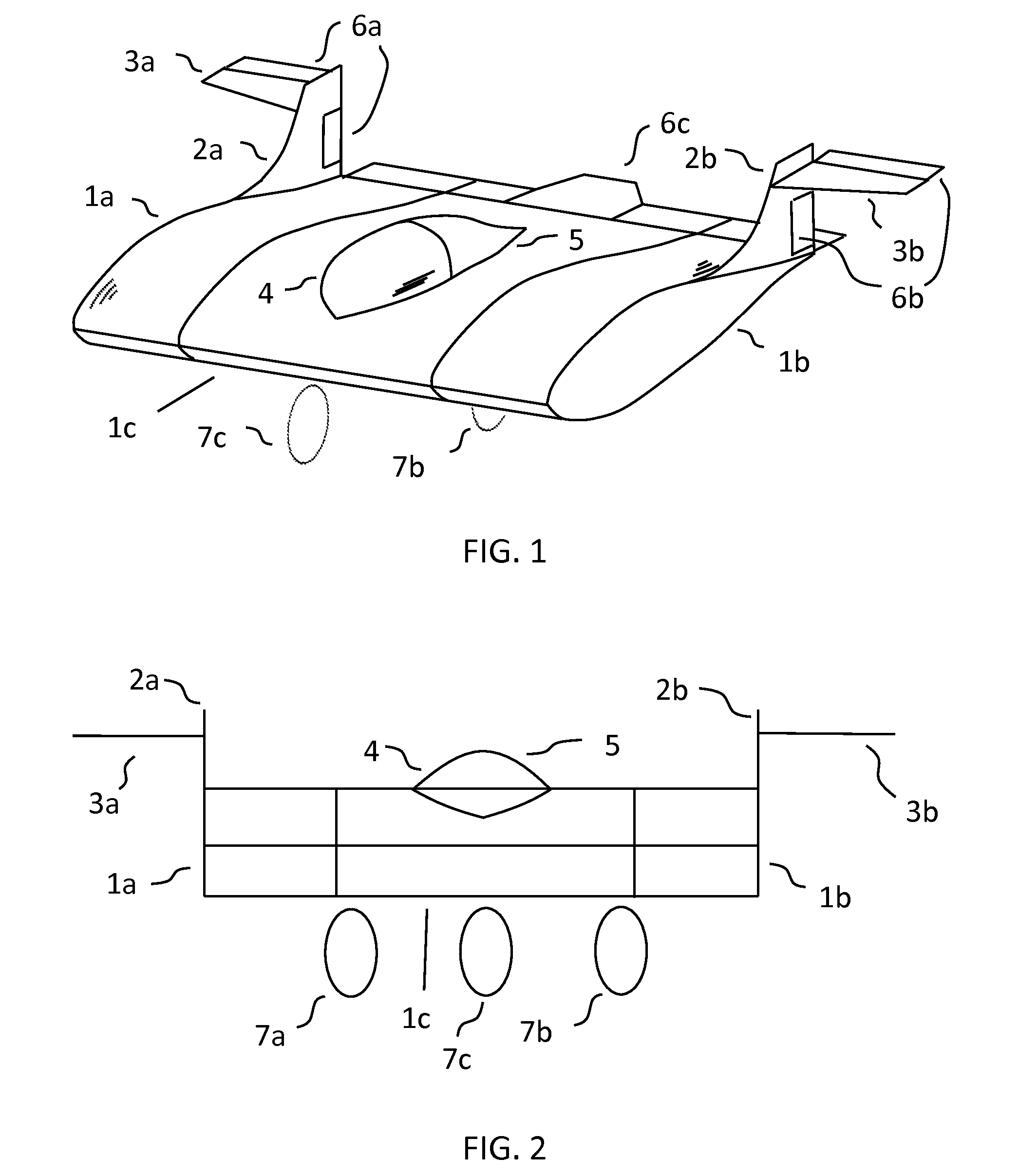
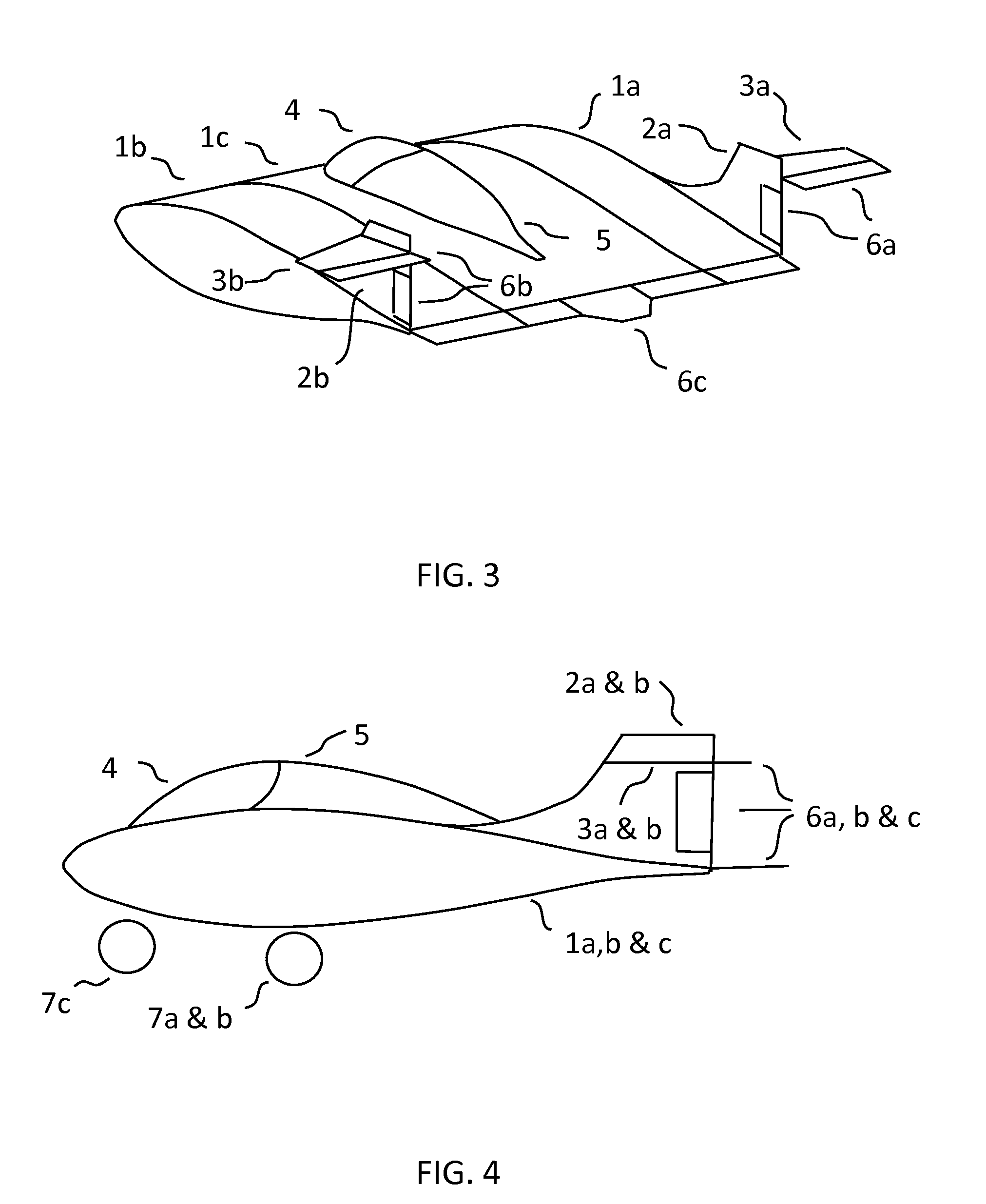
[0052]FIG. 1 is a front perspective of a first embodiment example illustrating portions of claimed disclosures. 1a, 1b, and 1c make up the main structure wing with 1a and 1b sections being laterally extendable and retractable to reduce or enlarge wing profile and surface area. 2a and 2b are possible vertical stabilizers. 3a and 3b are possible horizontal stabilizers configured outside of main structure wing turbulent boundary layer and vortices for improved control and efficiency. Item 4 illustrates one possible aerodynamic canopy configuration particularly useful for, but not limited to, manned versions of the vehicle. Item 5 illustrates one possible aerodynamic canopy fairing configuration to preserve aerodynamic efficiency of present canopies. 6a, 6b and 6c are possible configurations for moveable surfaces to...

example 2

[0058]A second embodiment example is a low aspect ratio flying wing leveraging aspects of disclosures with dihedral, with wing sweep, and without boundary layer control. Dihedral and wing sweep angles are selected from within the claimed disclosures to illustrate one possible variation.

[0059]FIG. 7 is a front perspective of a second embodiment example illustrating portions of claimed disclosures. 10a, 10b, and 10c make up the main structure wing with 10a and 10b sections being laterally extendable and retractable to reduce or enlarge wing profile and surface area. 2a and 2b are possible vertical stabilizers. 3a and 3b are possible horizontal stabilizers configured for improved control and efficiency. Item 4 illustrates one possible aerodynamic canopy configuration particularly useful for, but not limited to, manned versions of the vehicle. Item 5 illustrates one possible aerodynamic canopy fairing configuration to preserve aerodynamic efficiency of present canopies. 6a, 6b and 6c ar...

example 3

[0065]A third embodiment example is a low aspect ratio flying wing leveraging aspects of disclosures without dihedral, without wing sweep, and with boundary layer control.

[0066]FIG. 13 is a front perspective of a third embodiment example illustrating portions of claimed disclosures. 1a, 1b, and 1c make up the main structure wing with 1a and 1b sections being laterally extendable and retractable to reduce or enlarge wing profile and surface area. 2a and 2b are possible vertical stabilizers. 3a and 3b are possible horizontal stabilizers structure wing turbulent boundary layer and vortices for improved control and efficiency. Item 4 illustrates one possible aerodynamic canopy configuration particularly useful for, but not limited to, manned versions of the vehicle. Item 5 illustrates one possible aerodynamic canopy fairing configuration to preserve aerodynamic efficiency of present canopies. 6a, 6b and 6c are possible configurations for moveable surfaces to control vehicle orientation ...


PUM


Abstract

A low aspect ratio flying wing provides aerodynamic stability throughout the flight envelope with improved aerodynamic efficiency. Insufficient stability and reduced aerodynamic efficiency typical of low aspect ratio flying wings is improved through wing design and proper application and placement of horizontal stabilizers and boundary layer control. Lateral asymmetric boundary layer manipulation is employed to alter flying wing orientation in flight. Lateral extension and retraction of the main structure wing optimizes efficiency. This novel flying wing is not found in literature or “prior art” and provides improvement in aerodynamic stability and efficiency over previous designs. Given the large amount of research, literature, patents and activity in the field since the 1930's and the absence of a practical design indicates the non-obvious nature of these disclosures. In addition, those skilled in the art teach away from present disclosures failing to realize the better than predicted advantages.

Description

TECHNICAL FIELDField of the Invention[0001]This application takes advantage of the filing date of application Ser. No. 13 / 674,911, filed 12 Nov. 2012. This application takes advantage of filing date of the ornamental design application 29 / 437,045, filed 12 Nov. 2012. The field of this invention is a stable, aerodynamically efficient, low aspect ratio flying wing aircraft teaching wing character, tail configuration and boundary layer control.BACKGROUND ARTBackground of the Invention[0002]Flying wing aircraft have been proposed for over 80 years with very few successful commercial and military embodiments; reference a well written historical description on flying wings in U.S. Pat. No. 6,923,403 (PTL 24). This longstanding pursuit for viable advantageous flying wing designs is testament to the non-obvious nature of the field. While many assume aerodynamics is a completely characterized technical field, citing deterministic analytical computational fluid dynamics (CFD) simulation tools...

Claims


Application Information

Patent Timeline
IPC IPC(8): B64C39/10B64C1/00B64C5/10B64C21/06B64C25/34
CPCB64C39/10B64C5/10B64C2001/0045B64C25/34B64C21/06B64C1/0009B64C2230/20B64C3/10B64C5/08B64C21/025B64C2039/105Y02T50/10
Inventor FRIESEL, ERIC, WALTER
Owner FRIESEL ERIC WALTER
Why Eureka
Try Eureka