Light-Emitting Element, Compound, Display Module, Lighting Module, Light-Emitting Device, Display Device, Lighting Device, and Electronic Device
a technology of light-emitting elements and compound, which is applied in the direction of electroluminescent light sources, organic chemistry, thermoelectric devices, etc., can solve the problems of difficult development of substances to be light-emitting elements, and achieve the effects of low driving voltage, high emission efficiency, and high emission efficiency
- Summary
- Abstract
- Description
- Claims
- Application Information
AI Technical Summary
Benefits of technology
Problems solved by technology
Method used
Image
Examples
embodiment 1
[0091]A compound of one embodiment of the present invention which is described in this embodiment is a substance with a benzothienopyrimidine skeleton. A compound with the skeleton excels at transporting carriers (particularly electrons). Owing to this, a light-emitting element with low driving voltage can be provided.
[0092]The compound can have a high triplet excitation level (T1 level) and thus can be suitably used in a light-emitting element that uses an emission center substance that emits phosphorescence. Specifically, the high triplet excitation level (T1 level) of the compound can inhibit transfer of excitation energy of the phosphorescent substance, which leads to efficient conversion of excitation energy into light emission. A typical example of the phosphorescent substance is an iridium complex.
[0093]Note that a specific example of the benzothienopyrimidine skeleton is, but not limited to, a benzothieno[3,2-d]pyrimidine skeleton.
[0094]A preferred specific example of the co...
embodiment 2
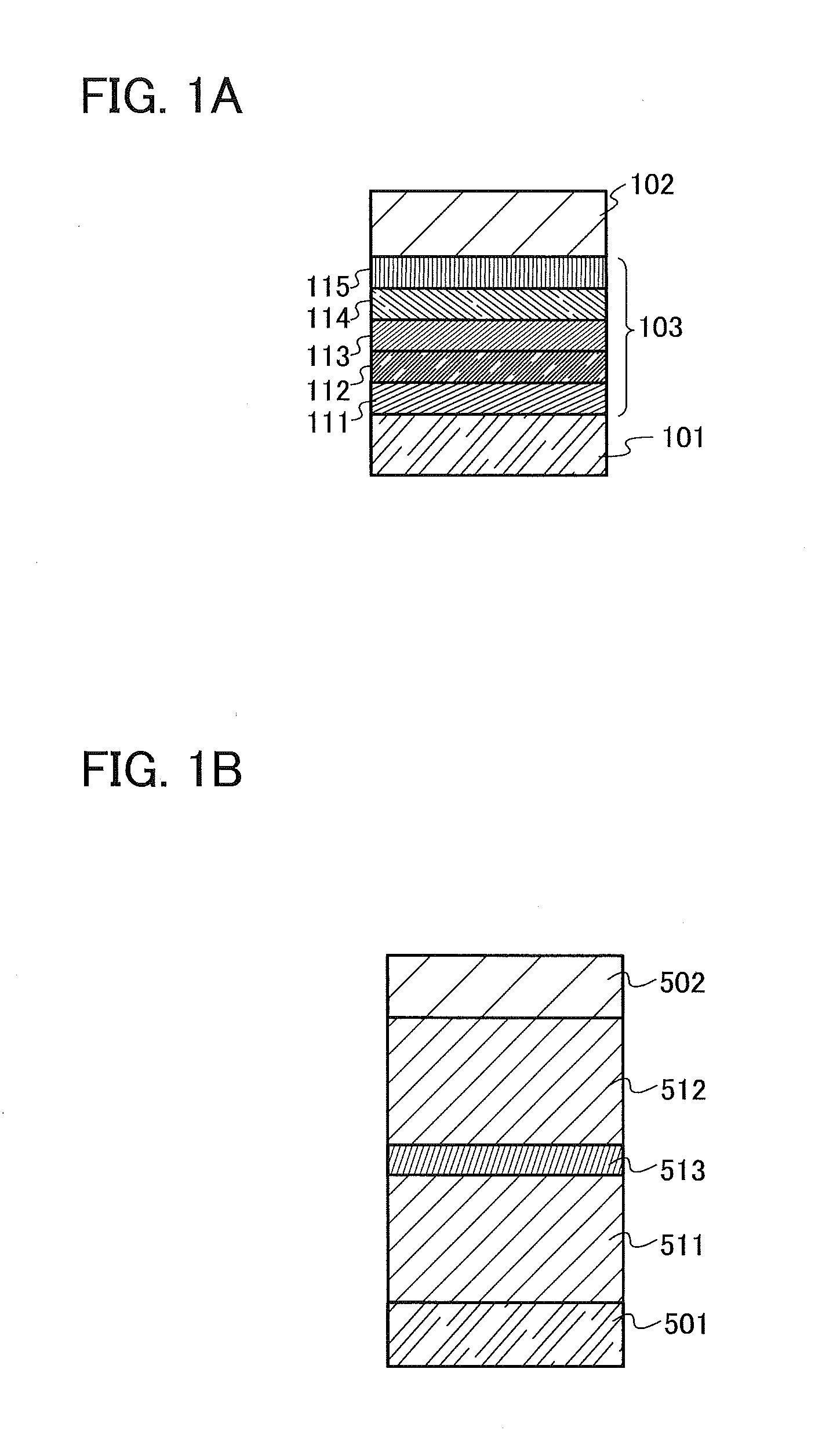
[0123]In this embodiment, one embodiment of a light-emitting element that includes a compound with a benzothienopyrimidine skeleton will be described with reference to FIG. 1A.
[0124]The light-emitting element of this embodiment has a plurality of layers between a pair of electrodes. In this embodiment, the light-emitting element includes a first electrode 101, a second electrode 102, and an EL layer 103 provided between the first electrode 101 and the second electrode 102. Note that in FIG. 1A, the first electrode 101 functions as an anode and the second electrode 102 functions as a cathode. That is, when a voltage is applied between the first electrode 101 and the second electrode 102 such that the potential of the first electrode 101 is higher than that of the second electrode 102, light emission is obtained. Of course, a structure in which the first electrode functions as a cathode and the second electrode functions as an anode can be employed. In that case, the stacking order of...
embodiment 3
[0183]In this embodiment is described one mode of a light-emitting element having a structure in which a plurality of light-emitting units are stacked (hereinafter, also referred to as stacked-type element), with reference to FIG. 1B. This light-emitting element includes a plurality of light-emitting units between a first electrode and a second electrode. Each light-emitting unit can have the same structure as the EL layer 103 which is described in Embodiment 2. In other words, the light-emitting element described in Embodiment 2 is a light-emitting element having one light-emitting unit while the light-emitting element described in this embodiment is a light-emitting element having a plurality of light-emitting units.
[0184]In FIG. 1B, a first light-emitting unit 511 and a second light-emitting unit 512 are stacked between a first electrode 501 and a second electrode 502, and a charge generation layer 513 is provided between the first light-emitting unit 511 and the second light-emi...
PUM
| Property | Measurement | Unit |
|---|---|---|
| work function | aaaaa | aaaaa |
| wavelength | aaaaa | aaaaa |
| work function | aaaaa | aaaaa |
Abstract
Description
Claims
Application Information
 - R&D
- Intellectual Property
- Life Sciences
- Materials
- Tech Scout
- Unparalleled Data Quality
- Higher Quality Content
- 60% Fewer Hallucinations
Browse by: Latest US Patents, China's latest patents, Technical Efficacy Thesaurus, Application Domain, Technology Topic, Popular Technical Reports.
© 2025 PatSnap. All rights reserved.Legal|Privacy policy|Modern Slavery Act Transparency Statement|Sitemap|About US| Contact US: help@patsnap.com


