Camera module and method for the production thereof

a technology of camera modules and production methods, applied in the field of camera modules, can solve the problems of long production times, one adjustment along one axis is possible in this way, and the time taken for the adhesive to cure predetermines the cycle time for the production of such a camera module, and achieves the effect of high precision and easy assembly

Active Publication Date: 2016-01-14
CONTI TEMIC MICROELECTRONIC GMBH
View PDF5 Cites 15 Cited by
  • Summary
  • Abstract
  • Description
  • Claims
  • Application Information

AI Technical Summary

Benefits of technology

[0013]Based on this state of the art, an aspect of the invention provides a camera module of the kind mentioned in the opening paragraph which has an easy-to-assemble structure without the drawbacks mentioned above but nevertheless allows the focus to be adjusted with high precision. A further aspect provides a method of manufacturing such a camera module according to the invention.

Problems solved by technology

The drawback of this is that only one adjustment along one axis is possible in this way.
However, this method has the following drawbacks, which are in particular due to the adhesive connection:An electrical connection between the support plate and the processing unit of the camera module is required.
The time taken for the adhesive to cure very often predetermines the cycle time for the production of such a camera module.
This entails long production times and hence high manufacturing costs, andThe adhesive connection must be stable over a long time in different environmental conditions, in particular in the automobile sector.
However, for the support to be movable, much assembly work is required, resulting in high manufacturing costs of the camera module.

Method used


Image

  • Camera module and method for the production thereof
  • Camera module and method for the production thereof
  • Camera module and method for the production thereof

Examples


Embodiment Construction

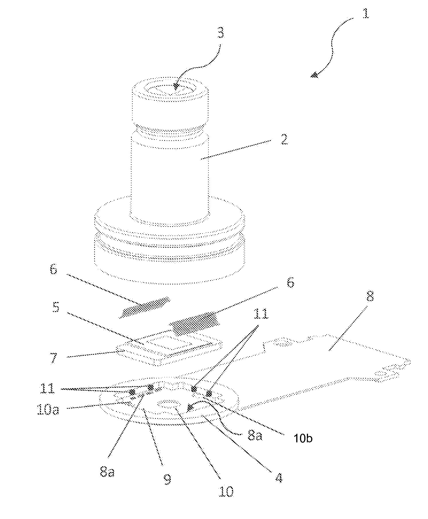
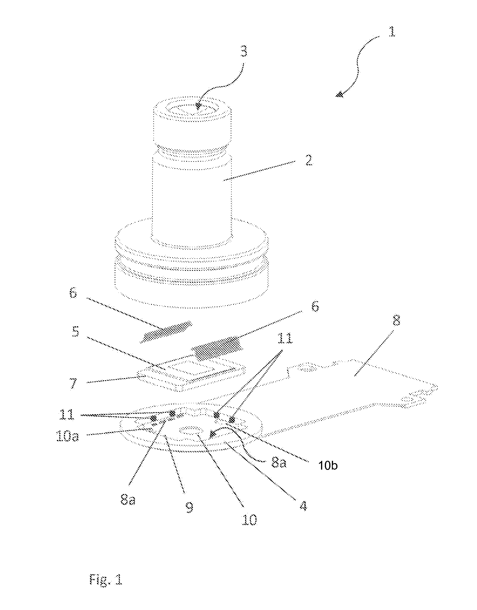
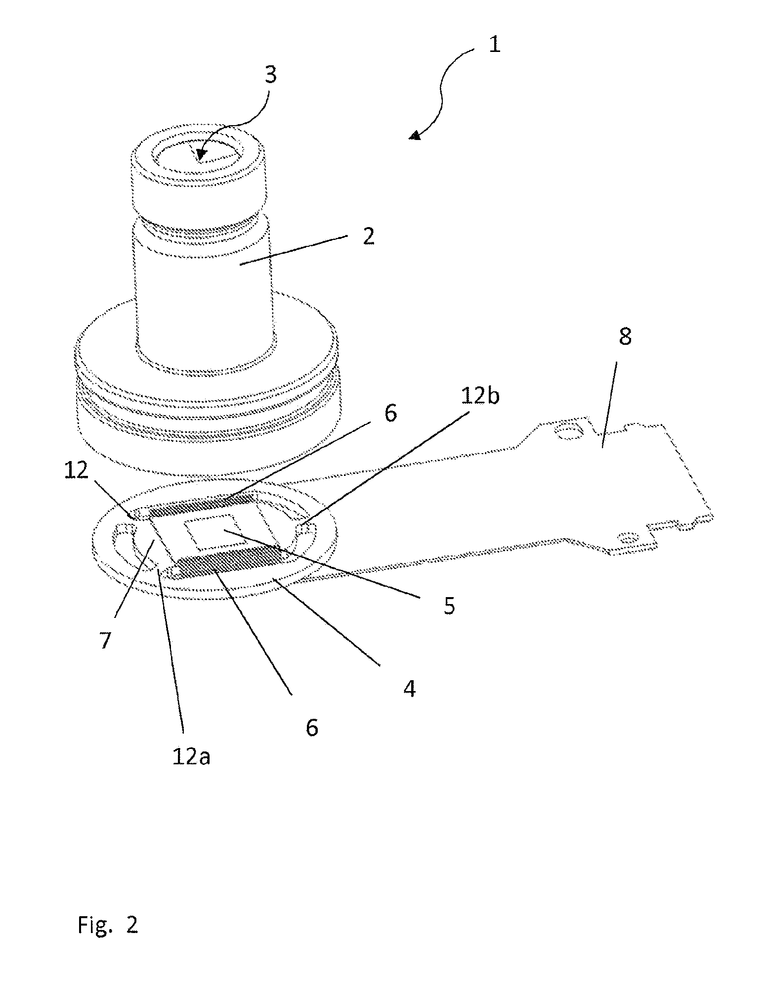
[0077]The first exemplary embodiment of a camera module 1 according to an aspect of the invention according to FIG. 1 comprises an objective lens housing 2 with an optical system 3 including several lenses (not visible in FIG. 1), which housing is connected to a support plate 4 in a force-based, shape-based or material-based manner, e.g. by pressing, welding, etc, an image sensor chip 5 arranged on a chip support 7, e.g. by means of an adhesive connection, as a “bar die” having wire bonding connections 6, a flexible printed circuit board 8 having wire bonding areas 8a for contacting the image sensor chip 5, and a circular support plate 4 having a recess 9 for receiving the chip support 7.

[0078]The support plate 4 and the chip support 7 are both mounted on the printed circuit board 8, so that the chip support 7 is placed within the recess 9 and rests flat on the printed circuit board 8, enclosed by the support plate 4. The flexible printed circuit board 8 is strip-shaped, so that one...


PUM


Abstract

A camera module including an objective lens housing with an optical system, an image sensor chip with wire bonding connections, and a printed circuit board for contacting the image sensor chip. The printed circuit board is designed with wire bonding areas to which the wire bonding connections of the image sensor chip are connected, and the assembly made up of the image sensor chip and the printed circuit board is designed in such a manner that the image sensor chip is focus-adjusted to the optical system by changing its position relative to the printed circuit board taking advantage of the flexibility of the wire bonding connections of the image sensor chip. The invention further relates to a method of manufacturing the camera module.

Description

CROSS REFERENCE TO RELATED APPLICATIONS[0001]This application is the U.S. National Phase Application of PCT / DE2014 / 200047, filed Feb. 11, 2014, which claims priority to German Patent Application No. 10 2013 102 819.5, filed Mar. 19, 2013, the contents of such applications being incorporated by reference herein.FIELD OF THE INVENTION[0002]The invention relates to a camera module comprising an objective lens housing with an optical system, a support plate on which the objective lens housing is supported, and an image sensor chip with wire bonding connections. The invention further relates to a method of manufacturing such a camera module according to the inventionBACKGROUND OF THE INVENTION[0003]Camera modules of this type installed in vehicles serve to record the surroundings of the vehicle in order to be able to use the image data for numerous functions, such as lane detection, traffic sign recognition, high-beam assistant, collision warning, pedestrian detection, etc., wherein the ...

Claims


Application Information

Patent Timeline
Patent Type & Authority Applications(United States)
IPC IPC(8): H04N5/225
CPCH04N5/2257H04N5/2254H04N5/2253H01L2924/0002H04N23/54H04N23/57H04N23/55H01L2924/00
Inventor MULLER, GERHARDKROKEL, DIETER
Owner CONTI TEMIC MICROELECTRONIC GMBH
Why Eureka
Try Eureka