Method of manufacturing fiber substrate and method of manufacturing resin rotator

a technology of fiber substrate and resin rotor, which is applied in the field of fiber substrate manufacturing and resin rotor manufacturing methods, can solve the problems of low flowability of thermosetting resin that can be dispersed in water, insufficient bonding strength between the fiber substrate and the metal bushing, and insufficient durability of the resin gear, so as to save time for one step, prolong the life of the mold, and reduce the effect of weigh

Active Publication Date: 2016-01-21
RESONAC CORP
View PDF3 Cites 5 Cited by
  • Summary
  • Abstract
  • Description
  • Claims
  • Application Information

AI Technical Summary

Benefits of technology

[0031]According to the present invention, a dispersion medium or water is poured onto the slurry diffusion member to cause the short fibers adhering to and remaining on the slurry diffusion member to fall down. This makes the weight (mass) of the fiber substrate to be manufactured uniform, and prevents the short fibers from being caught in a gap between molds to enable continuous production. This also extends the life of the mold.
[0032]If the step (c) of discharging the dispersion medium from the cylindrical mold and the step (d) of compressing the fiber aggregate are performed at the same time, the time for one step can be saved, and thus the fiber substrate can be manufactured in a shorter time.
[0033]If the step (c) of discharging the dispersion medium is performed under a reduced-pressure atmosphere, the dispersion medium can be discharged in a shorter time.
[0034]If the step (d) of compressing the fiber aggregate is performed while applying heat, the dispersion medium contained in the fiber aggregate can be discharged in a short time as in the case where the discharging of the dispersion medium can be performed under a reduced-pressure atmosphere. If heat is applied under a reduced-pressure atmosphere, the dispersion medium can be discharged in a further shorter time.
[0035]If the fiber aggregate is shaped like a gear in the cylindrical mold, a subsequent cutting step can be simplified when the final product to be fabricated is a gear, which improves the material yield.
[0036]In the resin rotator according to the present invention, the weight of the fiber substrate is uniform. Thus, the resin rotator has uniform strength and high durability, and can be used as a resin rotator that can endure high-temperature high-load use conditions in vehicle components, industrial components, and so forth.

Problems solved by technology

In addition, the bonding strength between the fiber substrates and the metal bushing may be insufficient.
Therefore, the durability of the resin gears may be insufficient depending on the usage.
However, a thermosetting resin that can be dispersed in water has low flowability and does not provide sufficient wettability at the interface between the thermosetting resin and the fibers, and therefore does not provide durability suitable for practical use.
In the method, however, it is difficult to dispose a metal bushing in a center portion of a resin rotator.
In addition, the poured resin may leak through the entire mold which is formed from a wire net or the like, thereby making it difficult to take out a formed object after the resin has been cured.
Moreover, the mold may be clogged, and may not be used over and over (continuous production).
However, JP 2007-138146 A does not disclose at all a method that improves the bonding strength between the fiber substrate and a metal bushing.
Further, the short fibers may be caught in a gap between molds when compressing the fiber aggregate, which may break the molds to interrupt continuous production.

Method used


Image

  • Method of manufacturing fiber substrate and method of manufacturing resin rotator
  • Method of manufacturing fiber substrate and method of manufacturing resin rotator
  • Method of manufacturing fiber substrate and method of manufacturing resin rotator

Examples


example 1

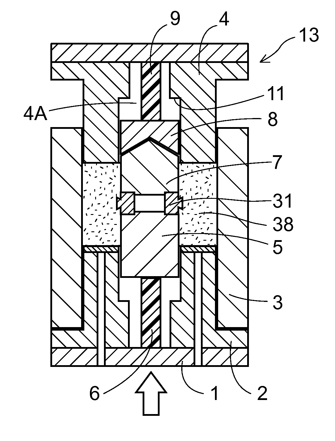
[0159]In order to prepare slurry, a tank filled with water in such an amount that short fibers would be dispersed at a concentration of 4 g / liter was prepared. Then, short fibers in such an amount that the total amount of the short fibers in the resin molded member would be 40% by volume were poured into the tank. Specifically, 45% by mass of para-aramid short fibers (“Technora (trademark of Teijin Ltd.)” manufactured by Teijin Ltd.) having a single fiber fineness of 1.7 dtex and a fiber length of 3 mm, 50% by mass of meta-aramid short fibers (“Teijinconex (trademark of Teijin Ltd.)” manufactured by Teijin Ltd.) having a single fiber fineness of 2.2 dtex and a fiber length of 3 mm, and 5% by mass of fine fibers obtained by fibrillating “Kevlar (trademark of DuPont) pulp” manufactured by DuPont to a freeness value of 300 ml were poured into the tank. Then, water in the tank was stirred by a stirrer to disperse the short fibers to prepare slurry.

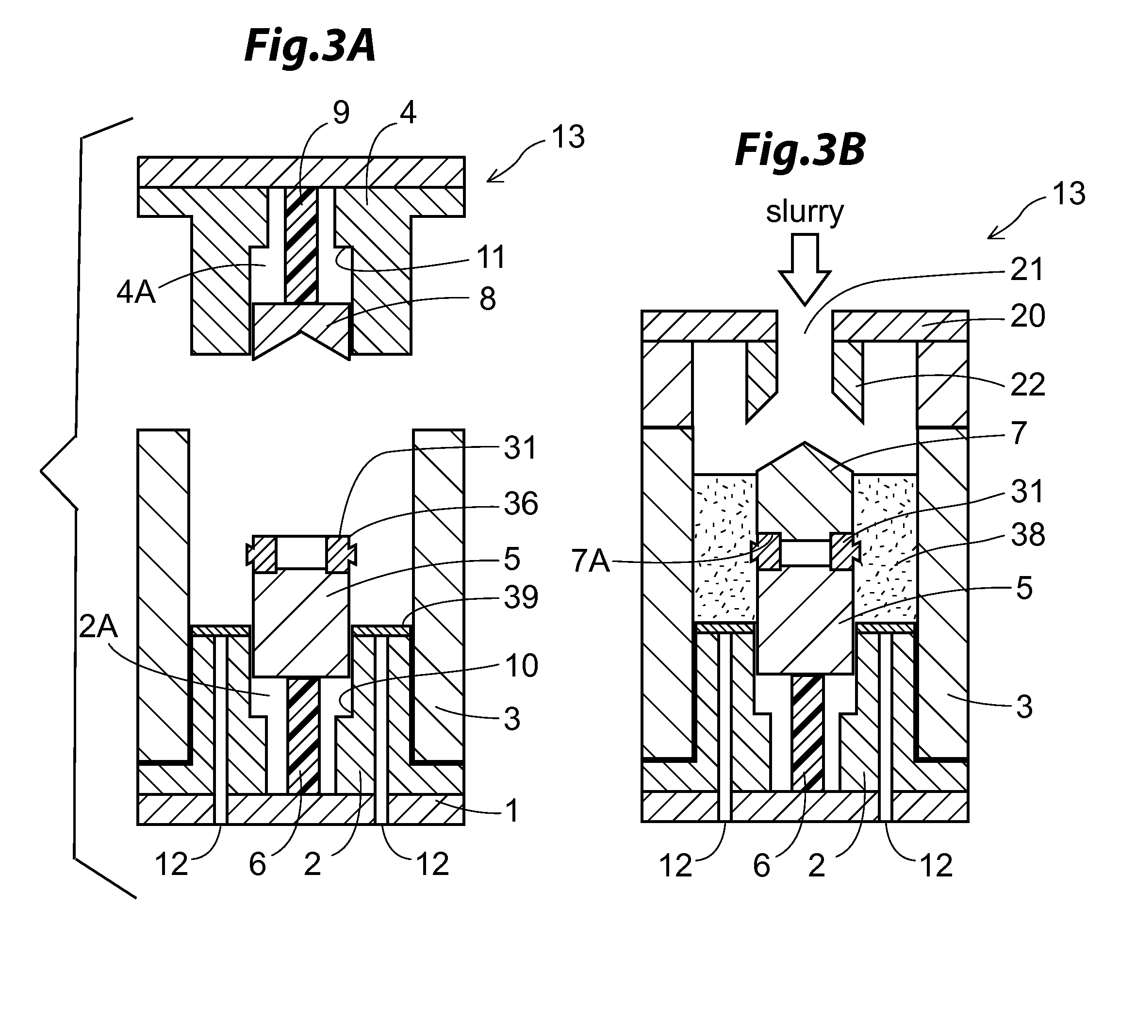
[0160]Next, the filtering-dehydration c...


PUM

PropertyMeasurementUnit
angleaaaaaaaaaa
diameteraaaaaaaaaa
lengthaaaaaaaaaa

Abstract

There is little fluctuation in amount of short fibers among individual products of fiber substrate. No damage is caused to a mold for the fiber substrate. Continuous production of the fiber substrates is possible. A method of manufacturing a fiber substrate includes the steps of: preparing slurry by dispersing short fibers in a dispersion medium; pouring the slurry into a cylindrical mold from above the cylindrical mold, the slurry being directed to a slurry diffusion member disposed in the center of the cylindrical mold and having an upward pointing conical or pyramidal shape; pouring the dispersion medium or water onto the slurry diffusion member from above the slurry diffusion member to cause the short fibers adhering to the slurry diffusion member to fall down, after the step of pouring the slurry; and discharging the dispersion medium from the cylindrical mold to accumulate the short fibers in the cylindrical mold to obtain a fiber aggregate.

Description

TECHNICAL FIELD[0001]The present invention relates to a method of manufacturing a fiber substrate using a filtering-dehydration system, and to a method of manufacturing a resin rotator made of the fiber substrate manufactured by the method.BACKGROUND ART[0002]A resin rotator in which a resin is retained in a fiber substrate has high durability, and is suitably used as the material of a resin gear or the like for use in vehicle components, industrial components, and so forth.[0003]JP 2001-295913 A describes a fiber substrate for fabrication of a resin gear. The fiber substrate is formed by weaving or knitting a thread into a tubular member and rolling the tubular member inside out from an end portion into a doughnut shape. JP 2001-295913 A also describes a resin gear formed by forming teeth on the fiber substrate which is impregnated with a resin so that the resin is retained in the fiber substrate.[0004]JP 2001-295913 A further describes a construction in which two fiber substrates ...

Claims


Application Information

Patent Timeline
Patent Type & Authority Applications(United States)
IPC IPC(8): B29C70/48B29C41/00B29C43/02B29C43/34B29C43/56B29C70/54
CPCB29C70/48B29C43/56B29C43/34B29C43/027B29C41/003B29C70/545B29K2705/12B29C2043/3488B29C2043/029B29K2101/10B29K2105/12B29K2277/10B29L2015/003B29C2043/563B29C43/18
Inventor OZAWA, MASAYASUGIYAMA, MASAO
Owner RESONAC CORP
Why Eureka
Try Eureka