Air-Enriched Gaseous Fuel Direct Injection For An Internal Combustion Engine

a gaseous fuel and direct injection technology, which is applied in the direction of liquid fuel feeders, machines/engines, electric control, etc., can solve the problems of increasing the cost of fuel systems, reducing the reliability or lifetime of components, and affecting the performance of the engin

Active Publication Date: 2016-01-21
WESTPORT FUEL SYST CANADA INC
View PDF5 Cites 38 Cited by
  • Summary
  • Abstract
  • Description
  • Claims
  • Application Information

AI Technical Summary

Benefits of technology

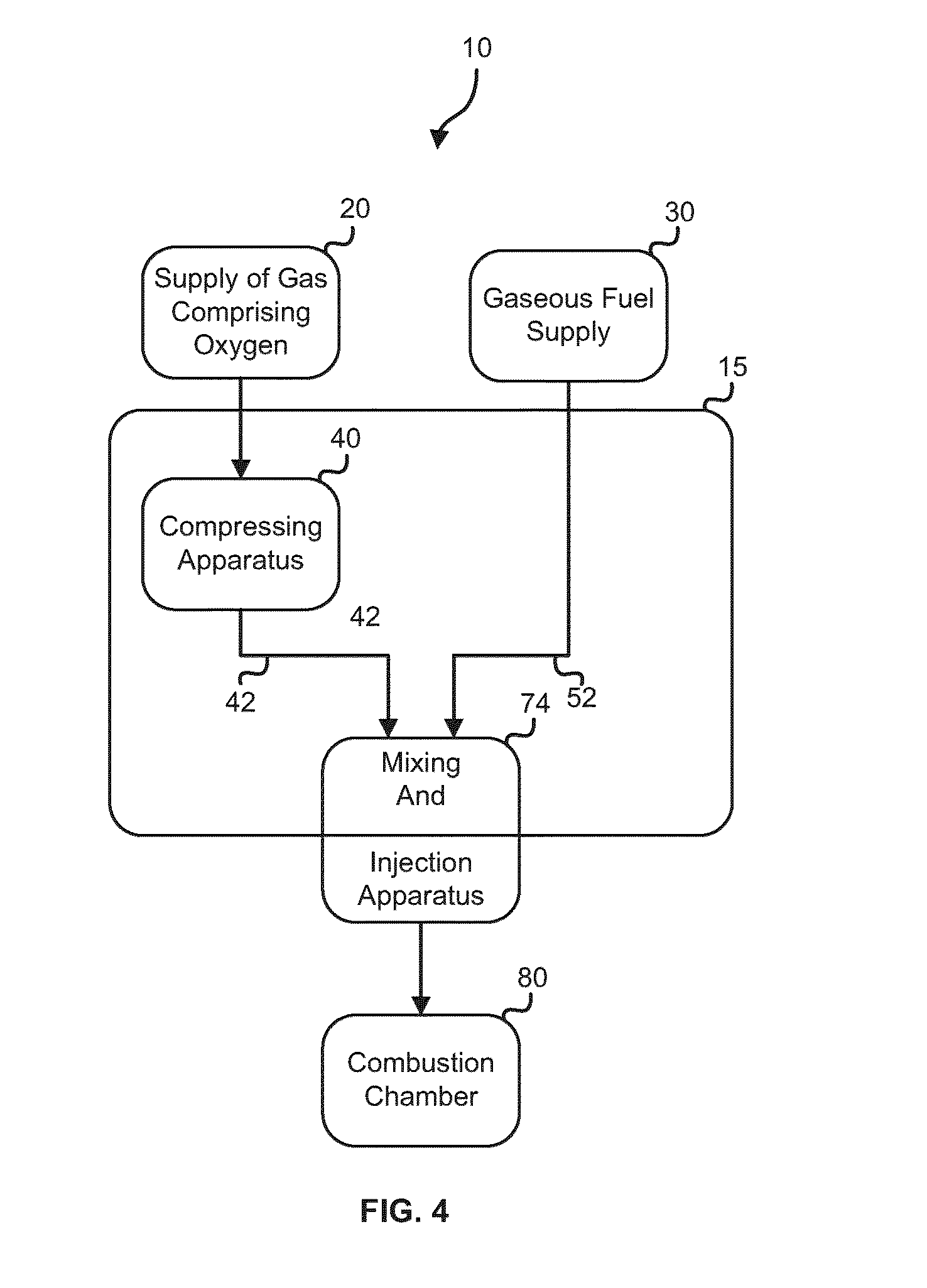
[0018]The first compressor can comprise a cylinder and a piston of the internal combustion engine that is employed as a first stage compression. In this embodiment, the apparatus further comprises an electronic controller; a check valve between the cylinder and the first storage operable to deliver a portion of air compressed by the piston in the cylinder during a compression stroke; and a control valve between the second storage and the mixing apparatus and operably connected with the electronic controller; whereby the electronic controller commands the control valve to meter a predetermined amount of the gas comprising oxygen into the mixing apparatus. A first pressure sensor provides a first pressure signal representative of gas comprising oxygen pressure upstream of the control valve; and a second pressure sensor provides a second pressure signal representative of gas comprising oxygen pressure downstream from the control valve. The electronic controller receives the first and second pressure signals and commands the control valve as a function of the first and second pressure signals and gaseous fuel pressure upstream of the mixing apparatus. The gaseous fuel pressure can be determined by one of an entry in an engine map and a third pressure sensor.

Problems solved by technology

However its application in natural gas engines has some severe obstacles.
First, a gaseous fuel system with higher pressure rating requires special design and material that significantly increases the fuel system cost while reducing the reliability or lifetime of the components.
Secondly, higher injection pressure that is suitable for high load conditions may not be suitable for lower load conditions (an issue with turn down ratio), and thus this puts more pressure on injector / fuel system design to cover a wide range of operating pressures for different load conditions.
Since little control can be applied to change the charge air motion once the engine design is fixed, optimization at different engine operating points is not feasible.
As an additional drawback, since charge air motion mainly affects the bulk motion of the charge, its effectiveness on local mixing is limited.
While optimization can be achieved under certain engine operating points, a global optimization over the engine map is difficult.
Its application is, however, limited by the response time of the injector (controller and driver), total injection duration and injector dynamics.
Its effectiveness on gaseous fuelled engines has not yet been proven.
An important issue none of the above techniques is able to fully address is transient behavior of the engine.
As a result, the engine experiences temporary “starvation” of oxidant, or in technique term, an increase of equivalence ratio which leads to elevated levels of PM and carbon monoxide (CO) in the exhaust.
The liquid fuel is mixed with compressed air in a fuel injector, since it is not practical to mix liquid fuel and air further upstream from the injector.

Method used


Image

  • Air-Enriched Gaseous Fuel Direct Injection For An Internal Combustion Engine
  • Air-Enriched Gaseous Fuel Direct Injection For An Internal Combustion Engine
  • Air-Enriched Gaseous Fuel Direct Injection For An Internal Combustion Engine

Examples


first embodiment

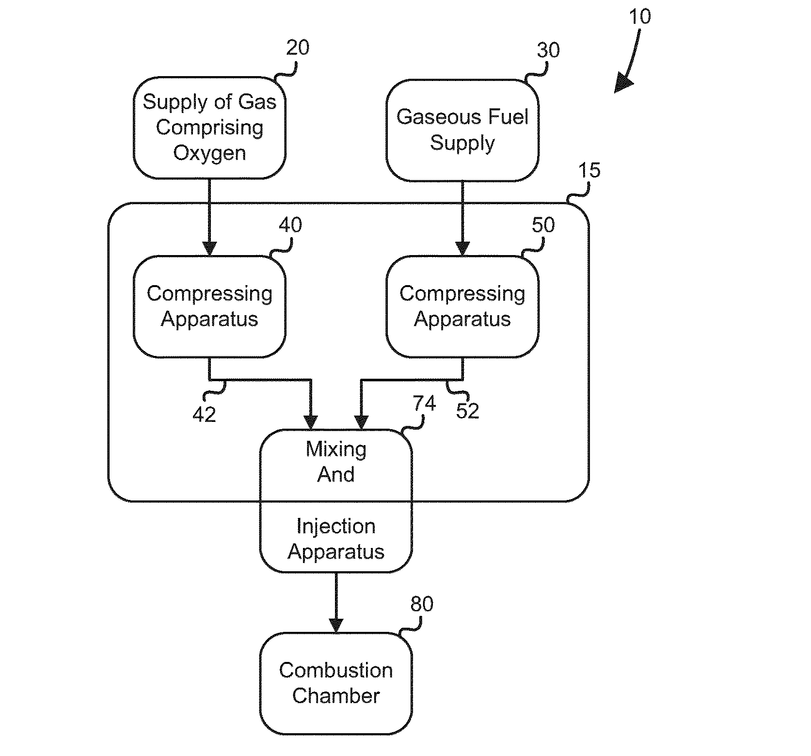
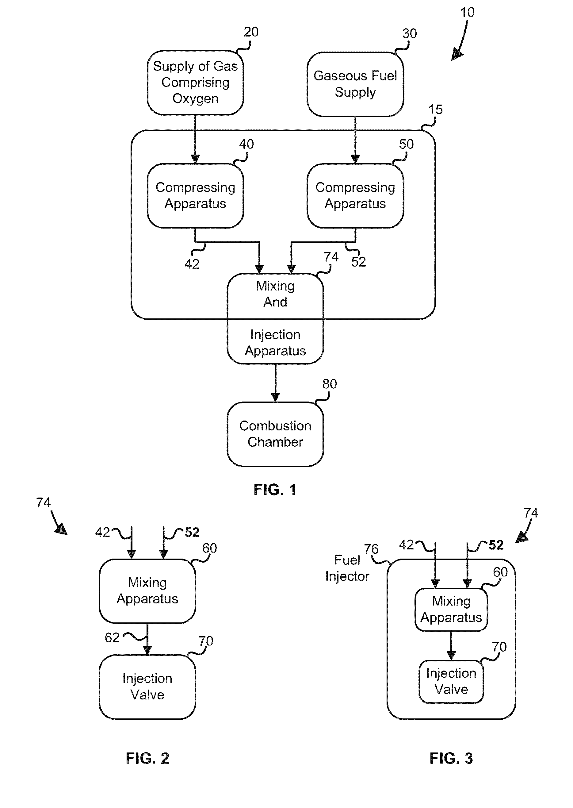
[0045]FIG. 1 shows direct injection apparatus 10 for an internal combustion engine comprising combustion chamber 80 according to a Direct injection apparatus 10 mixes gaseous fuel with a gas comprising oxygen, such as air, and introduces the non-ignitable mixture directly to combustion chamber 80. As used herein a gaseous fuel is defined as a fuel that is in a gaseous phase at standard temperature and pressure. Apparatus 10 comprises air supply 20 and gaseous fuel supply 30. Both supply 20 and 30 provide a low pressure supply of respective fluids. Mixture forming apparatus 15 forms a non-ignitable mixture of gaseous fuel and air in a predefined mixture mass ratio within a predetermined range of tolerance. The predefined mixture mass ratio, which could be defined as an equivalence ratio, can be adjusted as a function of engine operating conditions. Compressing apparatus 40 increases the pressure of air and compressing apparatus 50 increases the pressure of gaseous fuel to pressures ...

third embodiment

[0049]Referring to FIG. 5, there is shown direct injection apparatus 10 for the internal combustion engine according to a Mixture forming apparatus 15 comprises compressor 44 for compressing air from a low pressure in supply 20 to a pressure that is equivalent or higher than gaseous fuel pressure in piping 52. Low pressure air supply 20 can be air from an intake manifold for example, or from other sources. Compressed air is stored in high pressure storage 46, which can be piping and / or a vessel such as an accumulator. Gaseous fuel apparatus 34 comprises supply 30 and compressing apparatus 50 which employs conventional components to deliver pressurized gaseous fuel, and the selection of such components vary depending upon application requirements as would be known to those familiar with this technology. Gaseous fuel is stored in a liquid or gas state in apparatus 34, and alternatively apparatus 34 can receive gas from a residential or commercial gas line. A pumping apparatus (not sh...

fourth embodiment

[0050]Referring now to FIG. 6, there is shown direct injection apparatus 10 for the internal combustion engine according to a Air from supply 20 and gaseous fuel from supply 30 are mixed in mixing apparatus 90 such that the non-ignitable mixture in piping 92 has the predefined equivalence ratio. Mixing apparatus 90 can regulate the bias pressure between air in piping 22 and gaseous fuel in piping 32 such that the predefined equivalence ratio is achieved when mixing. Compressing apparatus 100 increases the pressure of the non-ignitable mixture in piping 92 and regulates the pressure of the non-ignitable mixture in piping 102. Injection valve 70 introduces the non-ignitable mixture in piping 102 directly in combustion chamber 80.

[0051]In all embodiments, there are several advantages to introducing a gaseous-fuel / air non-ignitable mixture into combustion chamber 80. Injecting a gaseous-fuel / air non-ignitable mixture results in enhanced turbulence level and duration since for a given a...


PUM


Abstract

A method for introducing a gaseous fuel into a combustion chamber of an internal combustion engine includes forming a non-ignitable mixture of the gaseous fuel and a gas including oxygen in a predefined mixture mass ratio within a predetermined range of tolerance having a pressure suitable for directly introducing the non-ignitable mixture into the combustion chamber during at least the compression stroke; and introducing the non-ignitable mixture directly into the combustion chamber.

Description

CROSS-REFERENCE TO RELATED APPLICATIONS[0001]This application is a continuation of International Application No. PCT / CA2013 / 050975 having a filing date of Dec. 17, 2013, entitled “Air-Enriched Gaseous Fuel Direct Injection for an Internal Combustion Engine”, which claimed priority benefits from Canadian patent application No. 2,798,870 filed on Dec. 17, 2012. The PCT / CA2013 / 050975 international application is hereby incorporated by reference in its entirety.FIELD OF THE INVENTION[0002]The present application relates to a technique of enriching a supply of gaseous fuel with a gas comprising oxygen prior to introduction into a combustion chamber of an internal combustion engine.BACKGROUND OF THE INVENTION[0003]Aftertreatment systems in current direct-injection natural gas engines are required to meet emission levels of the most stringent regulations. Due to the nature of the combustion process across the engine operating range, emission levels of particulate matter (PM), nitrogen oxid...

Claims


Application Information

Patent Timeline
Patent Type & Authority Applications(United States)
IPC IPC(8): F02M21/02F02B29/04F02B33/44F02B37/04F02B39/04F02B43/12F02B63/04F02D41/00F02D41/22F02D41/38F02M21/04H02K7/18
CPCF02M21/0245F02D2041/224F02M21/0209F02M21/0221F02B29/04F02B43/12F02M21/0287F02B37/04F02B63/04F02D41/38F02D41/0027F02D41/22F02B39/04F02M21/04F02B33/44H02K7/1815H02K7/1823F02D2041/389F02M21/0275F02M67/02F02B43/10F02B47/08F02M21/0218Y02T10/12Y02T10/30
Inventor HUANG, JIANHILL, PHILIP G.MUNSHI, SANDEEPMCTAGGART-COWAN, GORDON P.
Owner WESTPORT FUEL SYST CANADA INC
Why Eureka
Try Eureka