
Remote control apparatus and remote control system utilizing the apparatus

Active Publication Date: 2016-01-21
DENSO CORP
View PDF1 Cites 52 Cited by
  • Summary
  • Abstract
  • Description
  • Claims
  • Application Information

AI Technical Summary

Benefits of technology

This patent is about a remote control apparatus that can control an object through wireless communication. The technical effects of this invention are ensuring a high speed of control response by reducing the communication delay between the control object and the remote control apparatus. More specifically, the invention proposes a handling processing for addressing this problem. When the drive condition of the control object changes and the speed of control response becomes insufficient, the remote control apparatus reduces the communication delay by executing processing such as specifying positions on a route where the reception signal power may be insufficient, increasing the number of communication channels being used, commanding the control object to decrease the MCS index value, and so on. Overall, this invention allows for faster and more efficient control of objects through wireless communication.

Problems solved by technology

The communication delay may be calculated based on the level of communication quality obtained when the control object transmits information to the remote control apparatus, i.e., lowering of the communication quality will result in an increase of the communication delay.

Method used


Image

  • Remote control apparatus and remote control system utilizing the apparatus
  • Remote control apparatus and remote control system utilizing the apparatus
  • Remote control apparatus and remote control system utilizing the apparatus

Examples


first embodiment

1. First Embodiment

[1-1. Configuration]

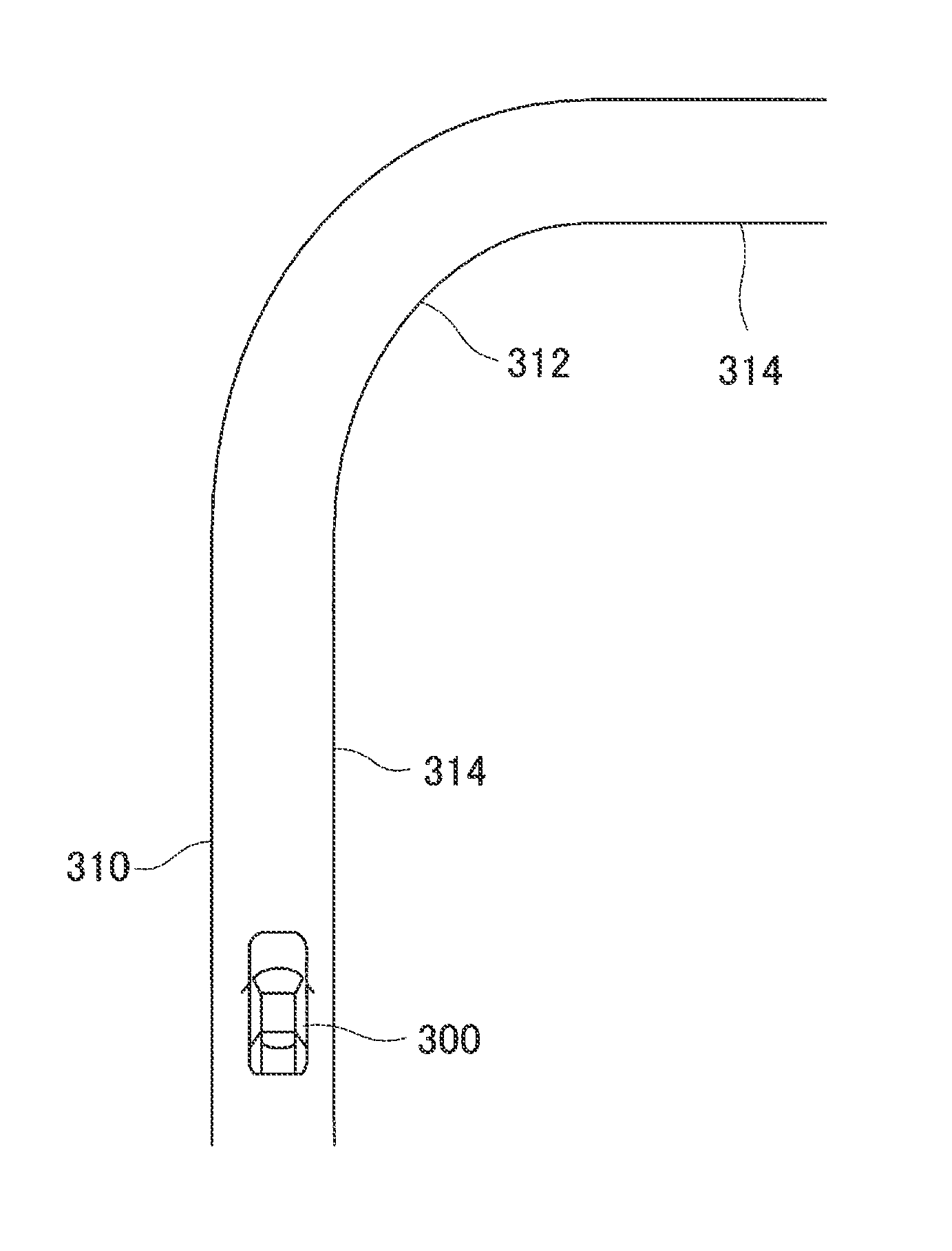
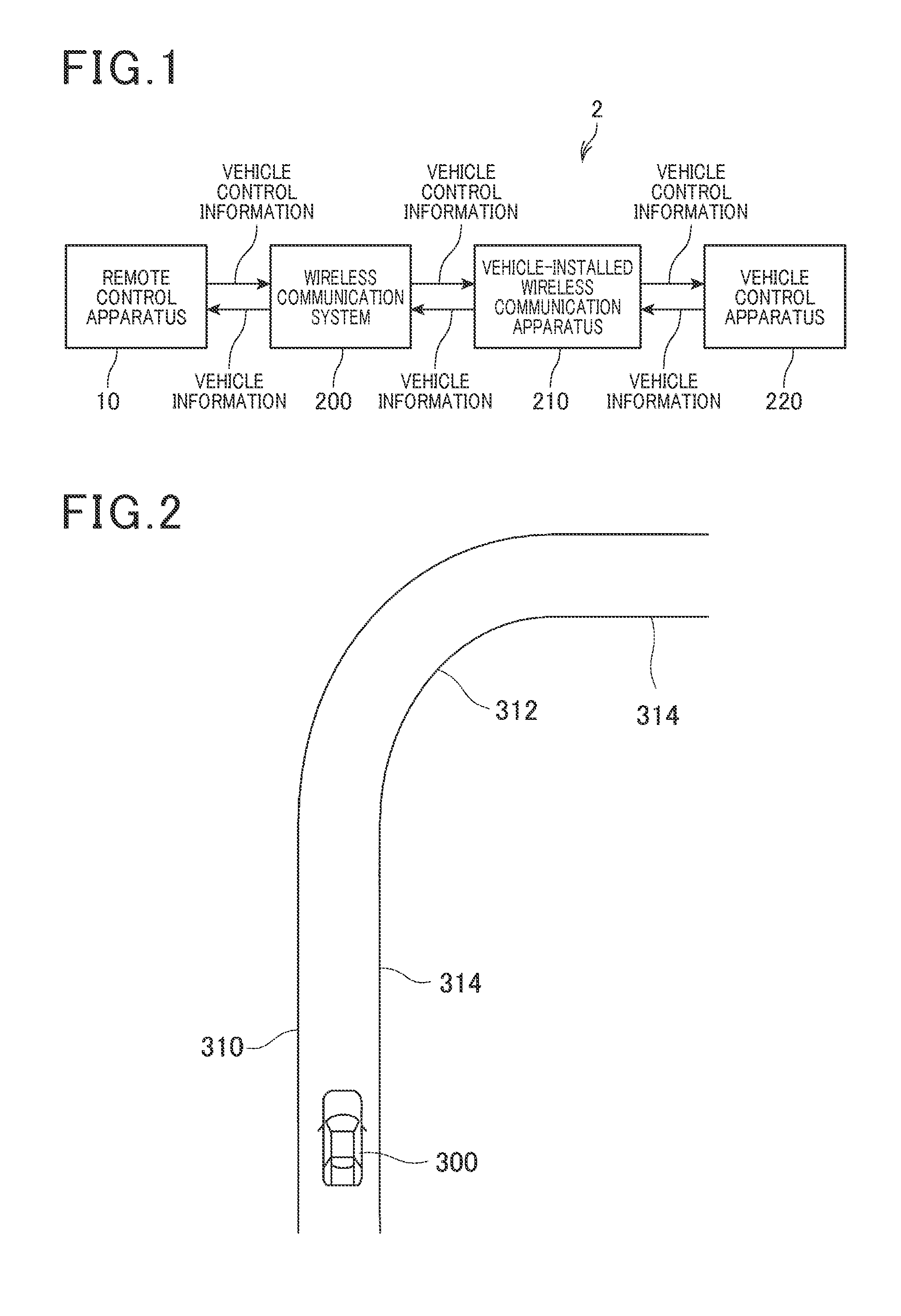
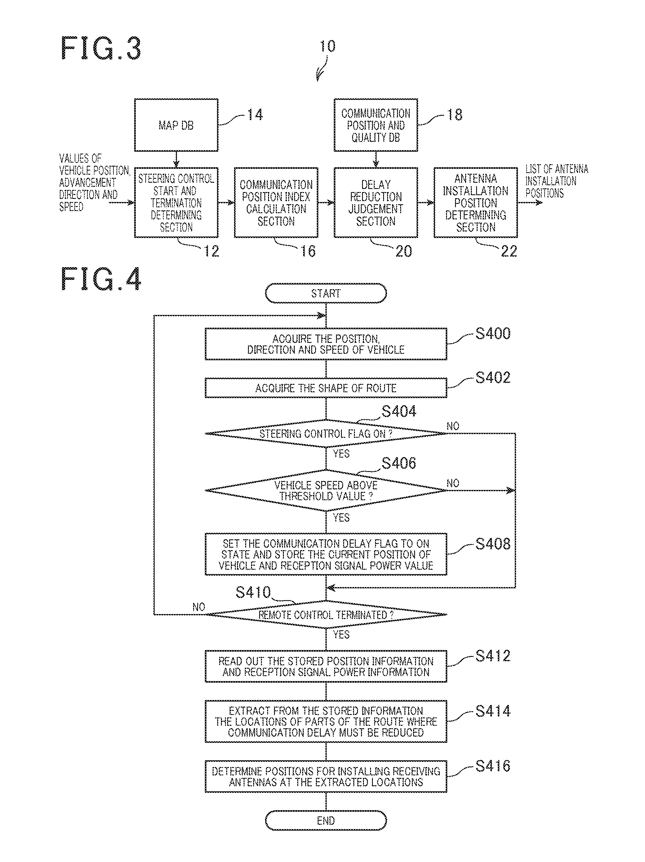
[0038]FIG. 1 is a block diagram showing the overall configuration of a first embodiment of a remote control system 2, which incorporates a remote control apparatus 10 connected to a wireless communication system 200, and a vehicle-installed wireless communication apparatus 210 and vehicle control apparatus 220 which are carried by a vehicle 300 shown in FIG. 2.

[0039]Control functions of the remote control apparatus 10 are performed by a computer in executing a remote control program that has been stored beforehand in a memory. The remote control apparatus 10 is installed at a central facility (remote control center), and performs remote control of the vehicle 300, which travels along a predetermined route 310. The remote control is performed using wireless communication between the remote control apparatus 10 and the vehicle 300.

[0040]The remote control apparatus 10 receives vehicle information transmitted from the vehicle 300, expressing the c...

second embodiment

2. Second Embodiment

[0073][2-1. Points of Difference from First Embodiment

[0074]The following description of a second embodiment is centered on points of difference from the first embodiment, with description of features common to the first embodiment being omitted.

[0075]The functions executed by a remote control apparatus 40 of the second embodiment are shown conceptually in the block diagram of FIG. 5. With the first embodiment, while the vehicle 300 is traveling along the route 310, the remote control apparatus 10 identifies those positions on the route at which the communication delay may be excessive, and stores corresponding information. After the vehicle 300 has completed driving along the route 310, the remote control apparatus 10 uses the stored information to determine positions where receiving antennas are to be installed for reducing the communication delay. With the second embodiment the remote control apparatus 40 executes processing for reducing the communication dela...

third embodiment

3. Third Embodiment

[0084][3-1. Points of Difference from Second Embodiment]

[0085]The following description of a third embodiment is centered on the points of difference from the second embodiment, with description of features common to the second embodiment being omitted.

[0086]The functions executed by a remote control apparatus 50 of the third embodiment are shown conceptually in the block diagram of FIG. 7.

[0087]With the second embodiment, when the vehicle 300 reaches a position along the route 310 at which it becomes necessary to reduce the communication delay, the remote control apparatus 40 commands the vehicle 300 to reduce the MCS index value used by the vehicle 300. With the third embodiment, when the vehicle 300 reaches a position where it is necessary to reduce the communication delay, the remote control apparatus 50 commands the vehicle 300 to transmit the vehicle information by multiplexed operation of a plurality of upstream communication channels. This is a point of di...


PUM


Abstract

A remote control apparatus uses wireless communication to control driving of a control object such as a vehicle. When the drive condition is changing, as when the vehicle is being steered to follow a curve in a travel route, while also the vehicle speed exceeds a specified threshold value, processing is executed for reducing a communication delay between the remote control apparatus and the control object, to thereby ensure sufficient speed of control response.

Description

CROSS-REFERENCE TO RELATED APPLICATIONS[0001]This application is based on and incorporates herein by reference Japanese Patent First Application No. 2014-148158 filed on Jul. 18, 2014.BACKGROUND OF THE INVENTION[0002]1. Field of Application[0003]The present invention relates to technology for remote control of a control object, using wireless communication.[0004]2. Description of Related Art[0005]Technology is known for employing wireless communication in remote control of a control object, for example as described in Japanese patent publication No. 5393240, designated in the following as reference 1. With the technology of reference document 1, image data are captured and transmitted through wireless communication by a control object (a mobile object such as a vehicle) and received by a remote operation apparatus and displayed by a display section of that apparatus. An operator of the remote operation apparatus performs remote control of the control object through wireless communic...

Claims


Application Information

Patent Timeline
IPC IPC(8): G05D1/00
CPCG05D1/0011G05D1/0022B60W30/00B60W30/10B60W2556/55B60W2552/00B60W2556/65B60W2552/15B60W2556/50
Inventor AKITA, HIDENORIKYO, TAKUMA
Owner DENSO CORP
Learn More