Using l1 cache as re-order buffer

a buffer and l1 technology, applied in the field of digital data processing, can solve problems such as the size of the buffer to reach an unacceptable siz

Active Publication Date: 2016-01-21
TEXAS INSTR INC
View PDF4 Cites 19 Cited by
  • Summary
  • Abstract
  • Description
  • Claims
  • Application Information

AI Technical Summary

Benefits of technology

[0003]A method is shown that eliminates the need for a dedicated reorder buffer to guarantee that the CPU requests are ...

Problems solved by technology

In high performance processors the size of this buffer may grow to an unacce...

Method used


Image

  • Using l1 cache as re-order buffer
  • Using l1 cache as re-order buffer
  • Using l1 cache as re-order buffer

Examples


Embodiment Construction

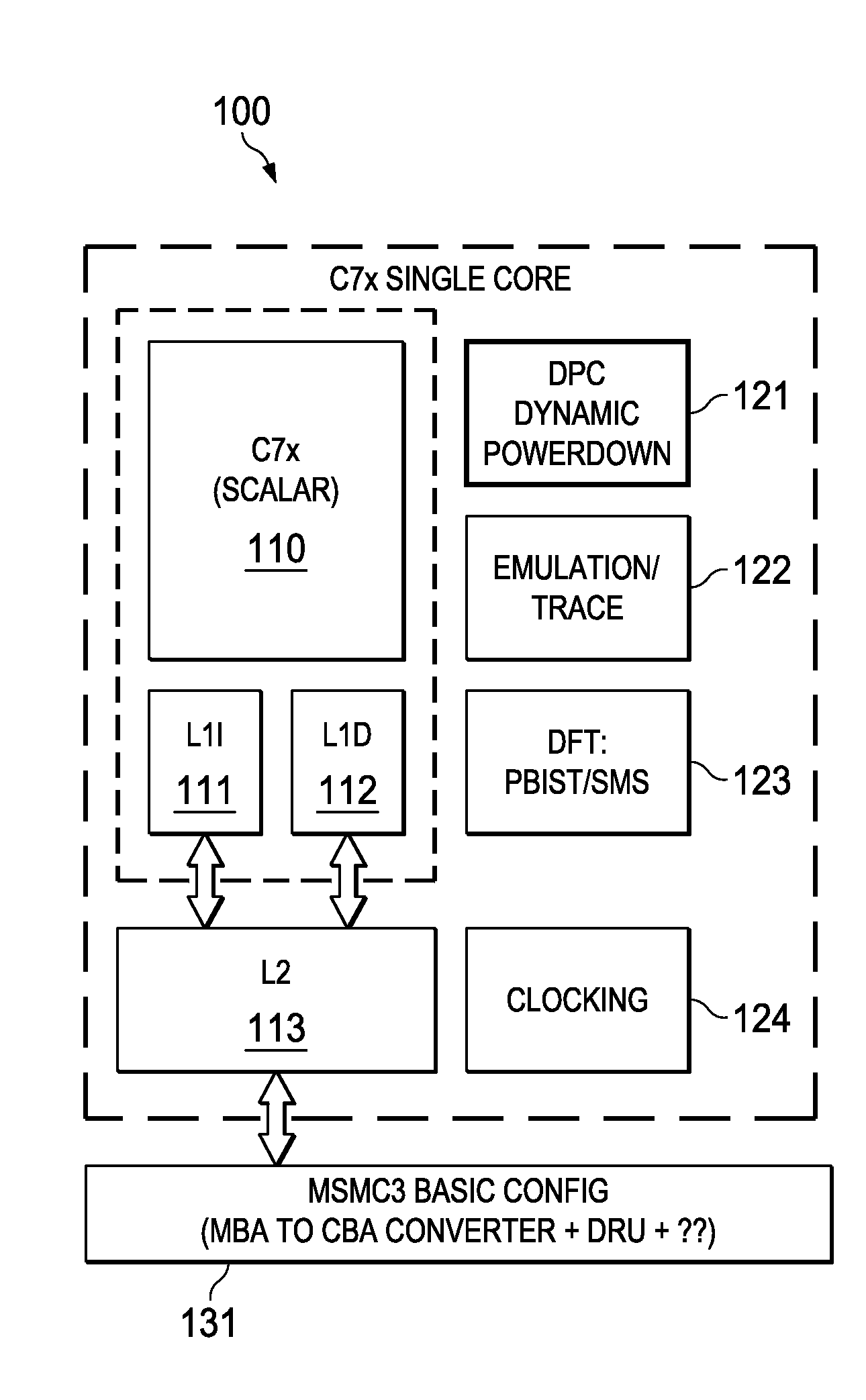
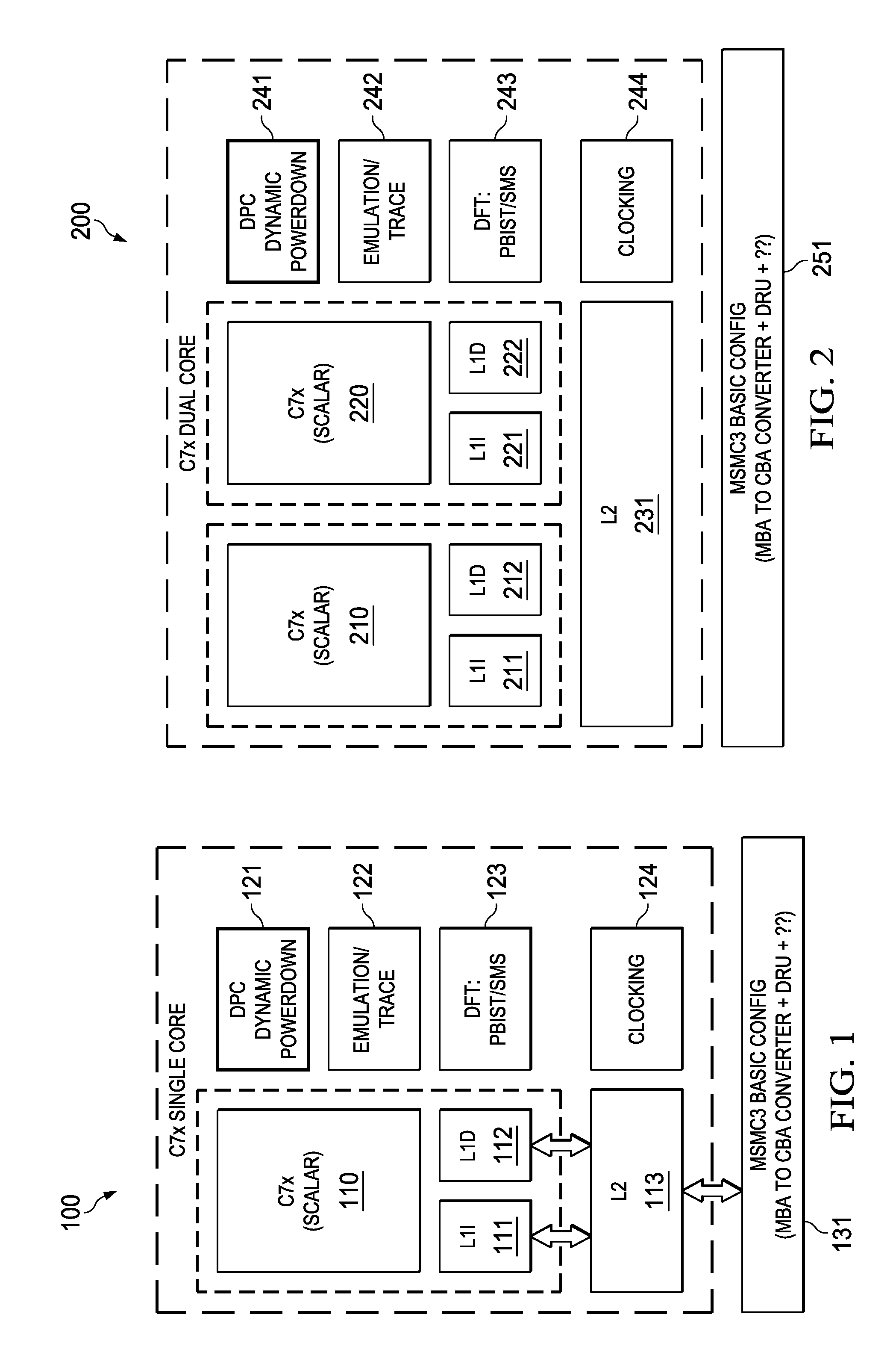
[0020]FIG. 1 illustrates a single core scalar processor according to one embodiment of this invention. Single core processor 100 includes a scalar central processing unit (CPU) 110 coupled to separate level one instruction cache (L1I) 111 and level one data cache (L1D) 112. Central processing unit core 110 could be constructed as known in the art and would typically include a register file, an integer arithmetic logic unit, an integer multiplier and program flow control units. Single core processor 100 includes a level two combined instruction / data cache (L2) 113 that holds both instructions and data. In the preferred embodiment scalar central processing unit (CPU) 110, level one instruction cache (L1I) 111, level one data cache (L1D) 112 and level two combined instruction / data cache (L2) 113 are formed on a single integrated circuit.

[0021]In a preferred embodiment this single integrated circuit also includes auxiliary circuits such as power control circuit 121, emulation / trace circ...


PUM


Abstract

A method is shown that eliminates the need for a dedicated reorder buffer register bank or memory space in a multi level cache system. As data requests from the L2 cache may be returned out of order, the L1 cache uses it's cache memory to buffer the out of order data and provides the data to the requesting processor in the correct order from the buffer.

Description

TECHNICAL FIELD OF THE INVENTION[0001]The technical field of this invention is digital data processing, and more specifically cache memories.BACKGROUND OF THE INVENTION[0002]In a digital signal processor having both level 1 instruction (L1), level 1 data (L1D) and level 2 (L2) cache memories, there is no guarantee that when the CPU requests data from the L2 cache the data will be returned in the order of the requests. This necessitates an additional step in the L1 cache to reorder the data before providing it to the CPU. This reordering has usually been done by a reorder buffer. In high performance processors the size of this buffer may grow to an unacceptable size as the allowable outstanding memory requests and packet sizes increase. The size of the reorder buffer has a direct impact on the frequency of operation of the high performance processor and also results in increased area for the core proportional to the size of the buffer.SUMMARY OF THE INVENTION[0003]A method is shown t...

Claims


Application Information

Patent Timeline
IPC IPC(8): G06F12/08
CPCG06F12/0833G06F2212/62G06F2212/283G06F12/0811G06F9/30036G06F9/30072G06F9/30094G06F9/30112G06F9/3013G06F9/3836G06F9/3853G06F9/3873G06F9/3834G06F9/3856G06F9/3838G06F9/38G06F12/0804G06F12/0828G06F12/0875G06F12/0897G06F2212/452G06F2212/60G06F2212/621
Inventor VENKATASUBRAMANIAN, RAMAKRISHNANOLORODE, OLULEYEONG, HUNG
Owner TEXAS INSTR INC
Why Eureka
Try Eureka