Integrated magnetcs transformer assembly

a transformer and integrated technology, applied in transformers/inductances magnetic cores, transformer/inductance voltage adjustment, electric variable regulation, etc., can solve the problems of serious damage to the driver circuitry and considerable power loss, and achieve the effect of reducing assembly costs, component costs, stock costs, and reducing the number of variants required

Active Publication Date: 2016-01-21
DANMARKS TEKNISKE UNIV
View PDF6 Cites 33 Cited by
  • Summary
  • Abstract
  • Description
  • Claims
  • Application Information

AI Technical Summary

Benefits of technology

[0024]Consequently, the same isolated power converter can be readily adapted to fit a variety of different power converter or inverter applications and therefore reduce the number of variants required of a particular power converter topology. Hence, the present isolated power converter is capable of lowering assembly cos...

Problems solved by technology

A common limitation of some known multiple-input power converters is that only a single input voltage or power source is allowed to transfer power or energy to the converter output at a time to prevent power coupling...

Method used


Image

  • Integrated magnetcs transformer assembly
  • Integrated magnetcs transformer assembly
  • Integrated magnetcs transformer assembly

Examples


Embodiment Construction

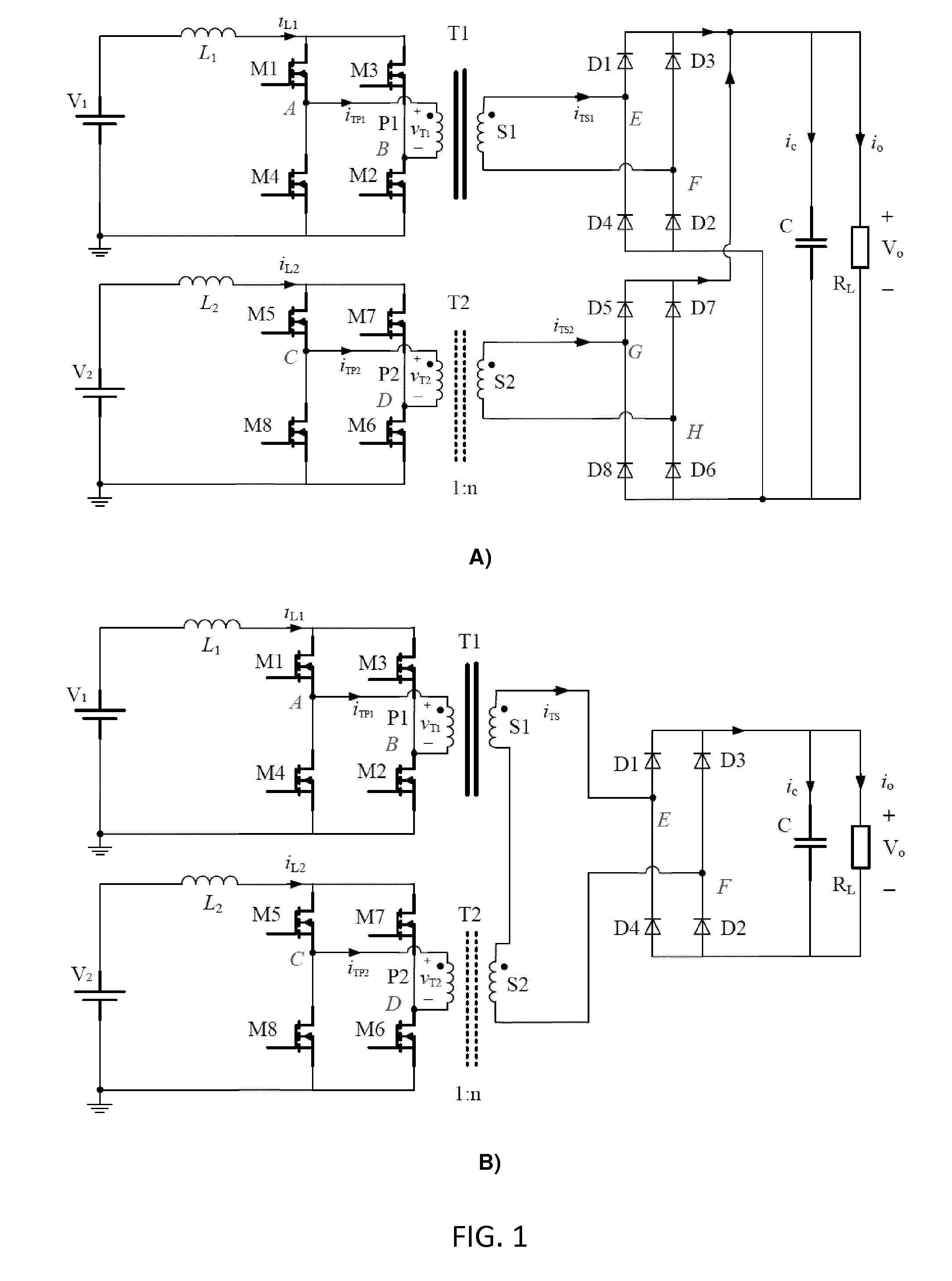
[0040]FIG. 1A shows a schematic drawing of a prior art dual-input isolated boost DC-DC power converter comprising two fully parallel converters and a common converter output. The power converter comprises two converter stages, build around transformer T1 and transformer T2, respectively, and operating fully in parallel with a common output capacitor C. The two transformers T1 and T2 are fully separate. The input inductor winding or primary winding of T1 is driven by a first H-bridge driver comprising MOSFET switches M1-M4 while the input inductor winding of T2 is driven by a second, separate, H-bridge driver comprising MOSFET switches M5-M8.

[0041]This prior art power converter possesses a boost-type structure or topology with a common output DC output across output capacitor C such that only one converter stage at a time is allowed to transfer energy from either of the DC input voltage sources V1 and V2 to the load RL. Otherwise, the other converter stage stops working because the H...


PUM


Abstract

The present invention relates to an integrated magnetics transformer assembly comprising a first magnetically permeable core forming a first substantially closed magnetic flux path and a second magnetically permeable core forming a second substantially closed magnetic flux path. A first input inductor winding is wound around a first predetermined segment of the first magnetically permeable core and a second input inductor winding is wound around a first predetermined segment of the second magnetically permeable core. The integrated magnetics transformer assembly further comprises a first output inductor winding comprising series coupled first and second half-windings wherein the first half-winding is wound around a second predetermined segment of the first magnetically permeable core and the second half-winding is wound around a second predetermined segment of the second magnetically permeable core. A second output inductor comprises series coupled first and second half-windings wherein the first half-winding is wound around a third predetermined segment of the first magnetically permeable core and the second half-winding is wound around a third predetermined segment of the second magnetically permeable core. The second half-winding of the first output inductor winding and the second half-winding of the second output inductor winding are configured to produce oppositely directed magnetic fluxes through the second substantially closed magnetic flux path and the first half-winding of the first output inductor winding and the first half-winding of the second output inductor winding are configured to produce aligned, i.e. in the same direction, magnetic fluxes through the first substantially closed magnetic flux path. The integrated magnetics transformer assembly is well-suited for use in a broad range of single input or multiple-input isolated power converter topologies.

Description

[0001]The present invention relates to an integrated magnetics transformer assembly comprising a first magnetically permeable core forming a first substantially closed magnetic flux path and a second magnetically permeable core forming a second substantially closed magnetic flux path. A first input inductor winding is wound around a first predetermined segment of the first magnetically permeable core and a second input inductor winding is wound around a first predetermined segment of the second magnetically permeable core. The integrated magnetics transformer assembly further comprises a first output inductor winding comprising series coupled first and second half-windings wherein the first half-winding is wound around a second predetermined segment of the first magnetically permeable core and the second half-winding is wound around a second predetermined segment of the second magnetically permeable core. A second output inductor comprises series coupled first and second half-windin...

Claims


Application Information

Patent Timeline
IPC IPC(8): H01F27/34H01F27/24H01F27/28H02M3/335H02M5/293H02M7/06H02M7/217
CPCH01F27/24H01F27/2804H02M3/33569H02M3/33576H01F27/34H02M7/217H02M5/293H01F2027/2809H02M7/06H02M1/10H02M3/285H02M3/33561H02M3/33573H02M3/33571H02M3/01H01F27/28
Inventor OUYANG, ZIWEIANDERSEN, MICHAEL A.E.
Owner DANMARKS TEKNISKE UNIV
Why Eureka
Try Eureka