Isothermal plasma CVD system for reduced taper in optical fiber preforms

a technology of optical fiber and isothermal plasma, which is applied in the direction of glass deposition burners, furnaces, instruments, etc., can solve the problems of limited ability, inability to make precise, and inability to reduce the creation of unwanted axial non-uniformities. , to achieve the effect of reducing the creation of unwanted axial non-uniformities

Inactive Publication Date: 2016-01-28
OFS FITEL LLC
View PDF7 Cites 0 Cited by
  • Summary
  • Abstract
  • Description
  • Claims
  • Application Information

AI Technical Summary

Benefits of technology

[0010]In particular, the isothermal plasma CVD apparatus is configured to create a relatively narrow deposition zone of well-defined boundaries, the deposition zone being restricted in position to a narrow region immediately upstream of the isothermal plasma. By limiting the extent of the deposition zone to this specific region, adjustments in the deposition parameters can be performed in real time to maintain the geometric and optical properties of the preform within defined bounds. A delivery system for the chemical species is configured to be able to change the flow rates of the various reagents under the control of a processor that also controls the movement of the isothermal plasma. In one embodiment, a flash evaporator system (in place of a bubbler system) has been found to improve the response time of the delivery system. Programmable arrangements for controlling the relative movement of the isothermal plasma with respect to the substrate tube (both velocity and location) thus overcome the tendency for the terminations of the substrate tube to develop tapers.
[0012]In another embodiment, the present invention defines a method of providing axial profile control of layers deposited within an optical fiber preform, including the steps of: inserting a preform substrate tube within a chemical vapor deposition (CVD) reactor; creating an isothermal plasma within the preform substrate tube and a deposition zone located upstream of the isothermal plasma, where the isothermal plasma and deposition zone are controlled to move in an axial direction back and forth within the substrate tube; introducing reagents into the deposition zone within the substrate tube from a delivery system that is configured to respond to control signals for changing the reagent composition and concentration; and controlling the movement of the plasma within the substrate tube and the flow of reagents into the deposition zone in a synchronized manner that creates the desired axial refractive index profile control of the layers deposited within the substrate tube.

Problems solved by technology

However, unwanted axial non-uniformities often occur in either one or both of these desired outputs and are typically most pronounced in the regions adjacent to the terminal points of the substrate tube that delineate the overall deposition area (these terminal non-uniform regions often referred to as “end tapers”).
As a result, the ability to make precise, local changes in the properties of the preform is extremely difficult.
While some of these techniques have been somewhat helpful in reducing the presence of end tapers, they are all of limited ability since none of these techniques is able to directly control the composition of the deposited glass material.
That is, these prior art techniques are not able to adjust, in real time, the actual concentration of the chemical reagents delivered to the deposition zone at a given time during the process, or at a given position along the substrate tube.
Indeed, the relatively long deposition zone associated with prior art systems inevitably creates an axial gradient in glass composition, which is yet another undesirable result.
The prior art relative velocity approaches are not feasible for these high speed systems.

Method used


Image

  • Isothermal plasma CVD system for reduced taper in optical fiber preforms
  • Isothermal plasma CVD system for reduced taper in optical fiber preforms
  • Isothermal plasma CVD system for reduced taper in optical fiber preforms

Examples


Embodiment Construction

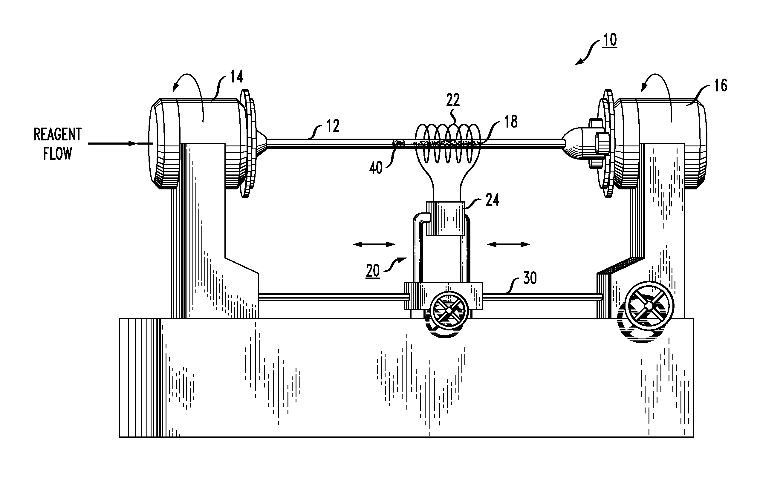
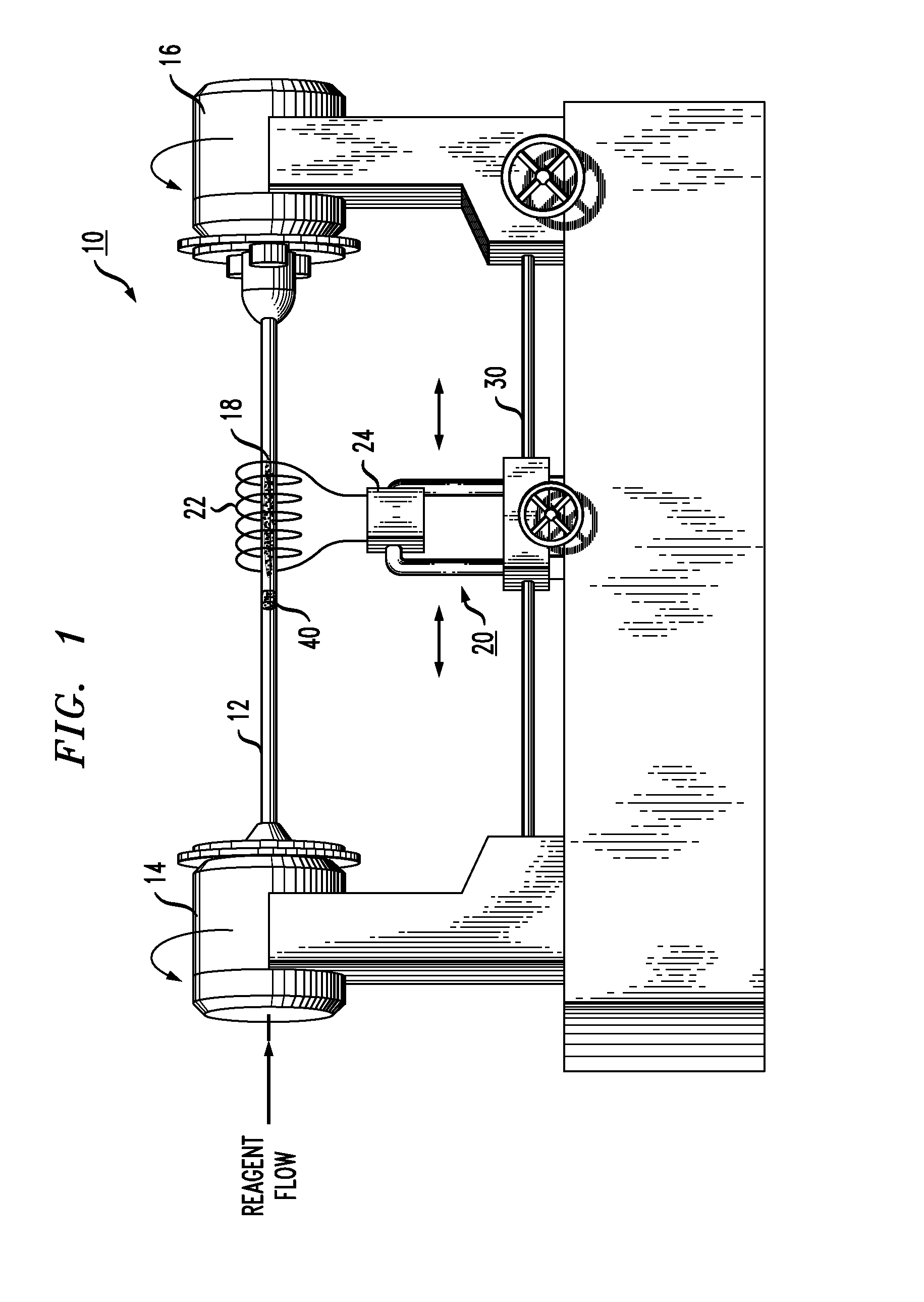
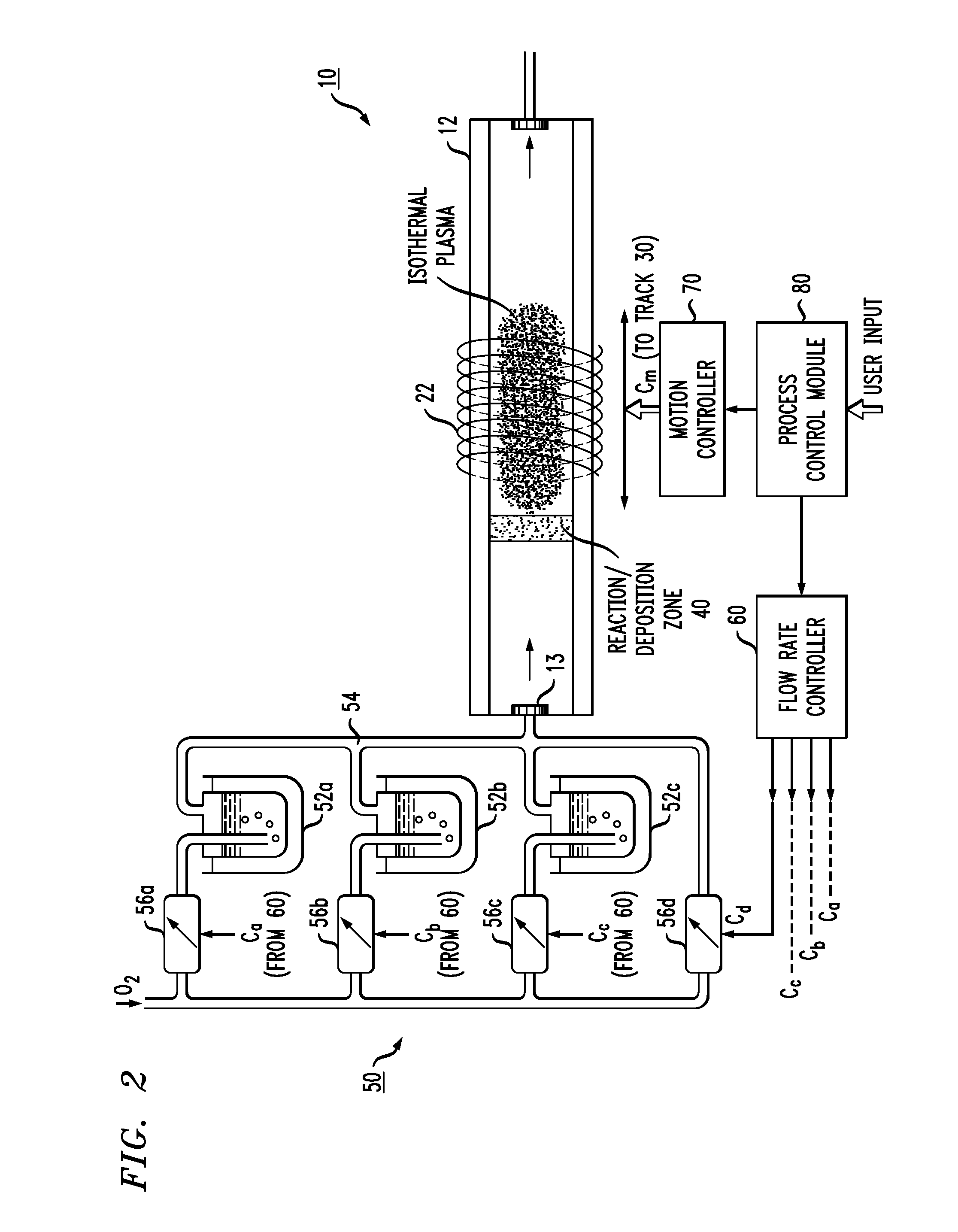
[0018]As will be discussed in detail below, the present invention relates to an isothermal plasma CVD apparatus and an associated method of fabricating optical fiber preforms that provides improved axial control of both cross-sectional area and refractive index profile of the preform. The apparatus and method are based upon the use of a low pressure (i.e., less than about 1 atm) isothermal plasma CVD process that creates a deposition hot zone that is narrowly confined to a region within the substrate tube that is immediately “upstream” of the isothermal plasma. The ability to create a narrow deposition zone (which is typically less than 5% of the total length of the substrate tube) allows for continuous modification of the deposition parameters and the ability to quickly respond and adjust the flows of the various constituents as necessary to maintain the desired axial refractive index profile shape. The ability to adjust reagent concentration as a function of elapsed process time a...


PUM

PropertyMeasurementUnit
lengthaaaaaaaaaa
pressureaaaaaaaaaa
lengthaaaaaaaaaa

Abstract

A chemical vapor deposition (CVD) system is configured to reduce the presence of geometrical and optical taper at the end sections of the preform, or more generally controlling the axial profile of the fabricated optical fiber preform. The system is configured to create an isothermal plasma within the substrate tube, with a relatively confined deposition zone located upstream of the plasma. A reagent delivery system is configured to adjust the composition and concentration of the introduced species in sync with the movement of the plasma and deposition zone within the substrate tube. By synchronizing the movement of the plasma with the adjustable reagent delivery system, it is possible to provide precision control of the axial profile of the created optical fiber preform.

Description

TECHNICAL FIELD[0001]The present invention relates to chemical vapor deposition (CVD) systems for creating optical fiber preforms and, more particularly, to an isothermal plasma CVD system that is particularly configured to reduce the creation of unwanted axial non-uniformities (in both geometry and composition), particularly occurring at the end sections of a preform substrate tube.BACKGROUND OF THE INVENTION[0002]Optical fiber preforms can be produced by chemical vapor deposition (CVD) techniques in which glass-forming chemical species are deposited on the inside of a silica substrate tube in a manner where the interior of the tube is coated with the deposited material. During the CVD process, vitreous glass or its soot precursor is deposited over a defined length of the substrate tube. In order to ultimately form an optical fiber of desired optical characteristics, it is important that the layers deposited during CVD exhibit a uniform cross-sectional area along the length of the ...

Claims


Application Information

Patent Timeline
Patent Type & Authority Applications(United States)
IPC IPC(8): C03B37/018
CPCC03B37/0183C03B2207/85C03B2207/70C03B2203/10C03B37/01807
Inventor ALONZO, JOHN C.BRAGANZA, DAVID D.BRODEUR, MERRILL H.FLEMING, JAMES W.
Owner OFS FITEL LLC
Why Eureka
Try Eureka