Dynamically adjustable acoustic panel device, system and method

a dynamic acoustic panel and panel technology, applied in the field of control of acoustics, can solve the problems of complex placement and sophisticated use, inability to typically be modified in real-time or dynamic manner, and failure of spaces with proper acoustic design for a specific us

Active Publication Date: 2016-01-28
LUHTALA ERIK J
View PDF9 Cites 9 Cited by
  • Summary
  • Abstract
  • Description
  • Claims
  • Application Information

AI Technical Summary

Benefits of technology

[0009]According to another aspect, a dynamic acoustic panel system comprises one or more dynamic acoustic panel devices covering at least parts of the walls and ceiling surrounding an enclosed area such as a room or other space, at least one acoustic sensor associated with the reflective surface of each panel device and configured to monitor sound in the enclosed area, one or more sensor modules receiving input from the sensors and configured to determine a current sound property level of the space such as current sound pressure levels, and a panel control unit which receives the current sound pro...

Problems solved by technology

Even spaces with proper acoustic design for a specific use often fail when subjected to the wide range of sound sources and levels required by modern multi-use venues and spaces.
The limitations of these systems are related to complexity, placement and sophisticated usage.
The passive acoustics of a space, which are the physical surfaces surrounding or enclosing the space (e.g. walls, ceiling, and floor) and their composition, contribute greatly to the acoustic characteristics but cannot typically be modified in a real-time or dynamic manner.
The physical surfaces may be designed to provide se...

Method used


Image

  • Dynamically adjustable acoustic panel device, system and method
  • Dynamically adjustable acoustic panel device, system and method
  • Dynamically adjustable acoustic panel device, system and method

Examples


Embodiment Construction

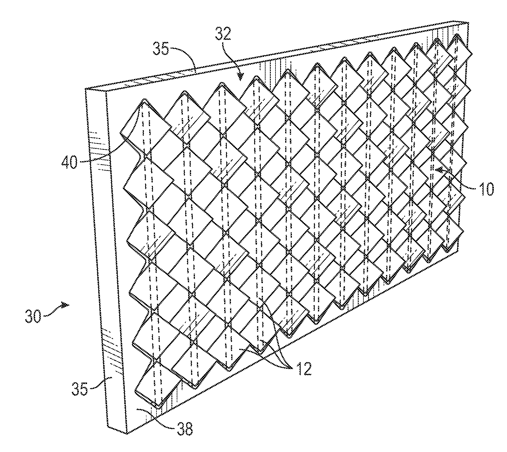
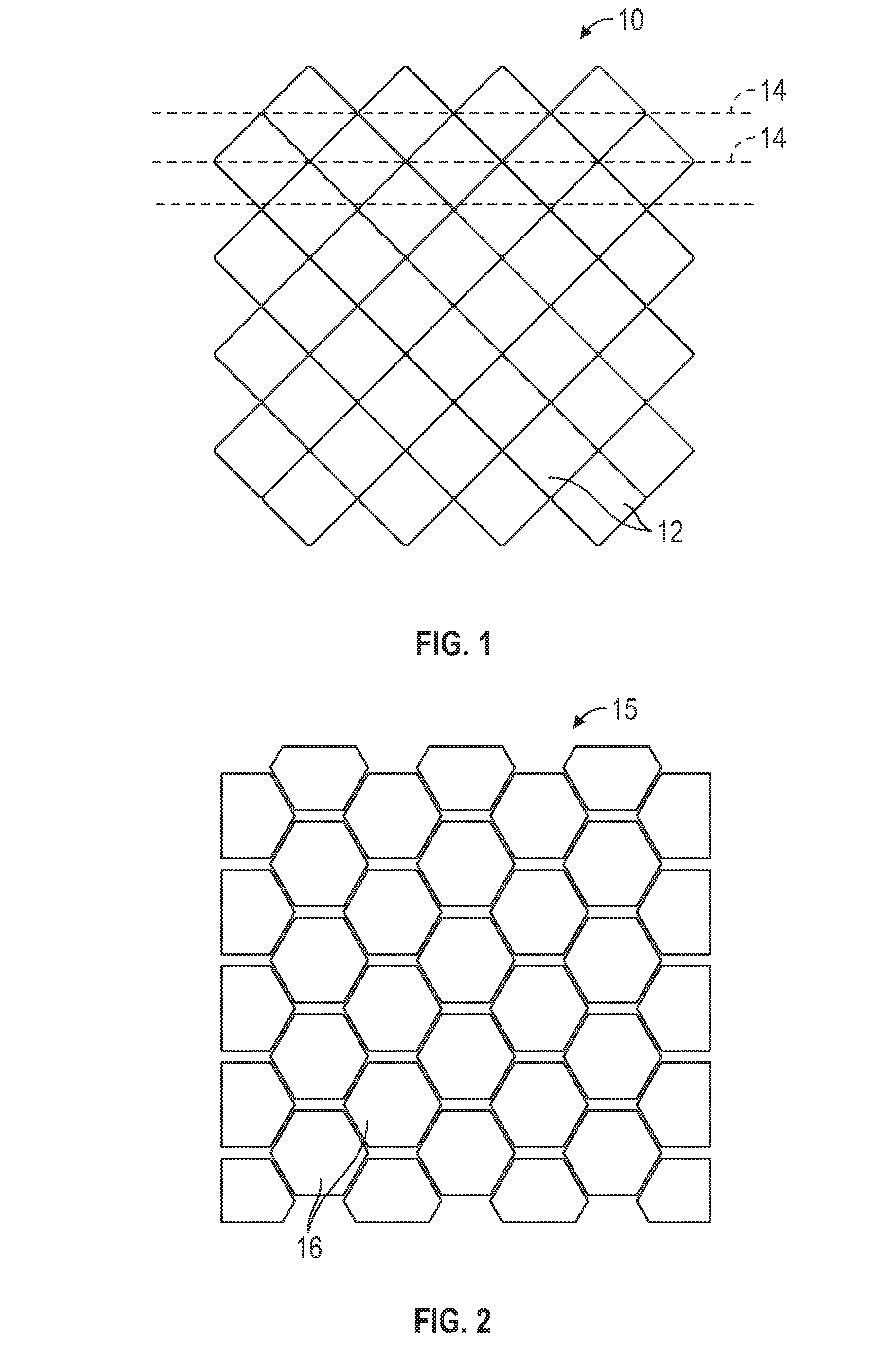
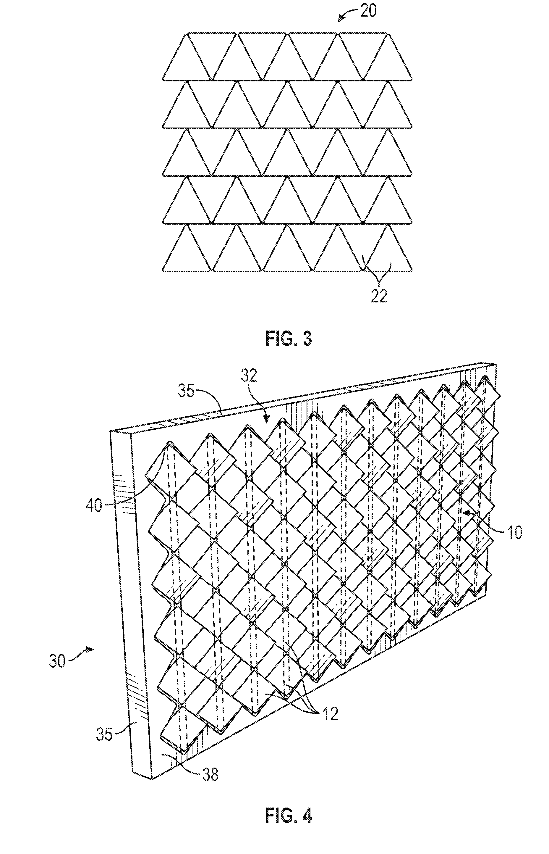
[0034]Certain embodiments as disclosed herein provide for a dynamic passive acoustic panel for mounting on a wall or ceiling of an enclosed space which is continuously adjustable to vary between a maximum reflection condition and a maximum absorption condition.

[0035]The subject matter described herein is taught by way of example implementations. Various details have been omitted for the sake of clarity and to avoid obscuring the subject matter. The examples shown below are directed to devices, systems and methods for controlling acoustics within an interior space in a building. Features and advantages of the subject matter should be apparent from the following description.

[0036]After reading this description it will become apparent to one skilled in the art how to implement the invention in various alternative embodiments and alternative applications. However, all the various embodiments of the present invention will not be described herein. It is understood that the embodiments pre...


PUM


Abstract

A dynamic passive acoustic panel device comprises an enclosure having a front opening, an absorbent panel of sound absorbent material mounted in the enclosure behind the front opening, and a reflective surface mounted in the front opening in front of the absorbent panel. The reflective surface comprises a tessellated array of reflective panels of matching shape arranged in a series of rows, each row being mounted for rotation about a central axis so as to vary the angle of inclination of the reflective panels in each row relative to the absorbent panel from zero degrees to ninety degrees to the absorbent panel, so as to vary the reflection and absorption characteristics of the panel device. A control system controls rotation of the rows of reflective panels, so as to vary the reflection and absorption levels between maximum reflection and maximum absorption based on desired acoustic properties of a space in which the panel device is located.

Description

BACKGROUND[0001]1. Related Field[0002]The subject matter discussed herein relates generally to control of acoustics within an interior space in a building, and is particularly concerned with a dynamic acoustic panel device, system and method.[0003]2. Related Background[0004]The acoustics of built spaces have a significant impact on the subjective perception of the quality of a space. Even spaces with proper acoustic design for a specific use often fail when subjected to the wide range of sound sources and levels required by modern multi-use venues and spaces. Most current systems for dealing with architectural acoustic issues in real-time rely on active acoustics which are electroacoustic solutions composed of microphones and loudspeakers. The limitations of these systems are related to complexity, placement and sophisticated usage. The passive acoustics of a space, which are the physical surfaces surrounding or enclosing the space (e.g. walls, ceiling, and floor) and their composit...

Claims


Application Information

Patent Timeline
IPC IPC(8): E04B1/84
CPCE04B1/84E04B9/001E04B9/0428E04B1/994
Inventor LUHTALA, ERIK, J.
Owner LUHTALA ERIK J
Why Eureka
Try Eureka