Unlock instant, AI-driven research and patent intelligence for your innovation.
A variable pitch fan and a method for varying the blade pitch in a fan
Inactive Publication Date: 2016-01-28
CNH IND AMERICA LLC
View PDF10 Cites 11 Cited by
Summary
Abstract
Description
Claims
Application Information
AI Technical Summary
This helps you quickly interpret patents by identifying the three key elements:
Problems solved by technology
Method used
Benefits of technology
Benefits of technology
The invention relates to a method for varying the pitch of blades on a fan without using hydraulic or pneumatic fluids. This simplifies the structure of the fan and avoids the need for complicated sealing systems. The method allows for easy and effective variation in blade pitch while the fan is in use.
Problems solved by technology
However, using a hydraulic or pneumatic fluid for actuating the adjusting device makes the fan quite complicated and hence expensive, particularly due to the risks of leakage of the hydraulic or pneumatic fluid.
For example, in hydraulic systems it is necessary to use rotating sealing elements which need to be replaced quite often since they tend to wear rapidly.
Similar drawbacks occur in connection with pneumatic systems.
Method used
Image
Click on the blue label to locate the original text in one second.
Reading with bidirectional positioning of images and text.
Examples
first embodiment
[0132]In a first embodiment, shown in FIG. 7, the calibration procedure can be carried out each time the vehicle is started up.
[0133]In this embodiment, which is particularly simple, when the vehicle is started up (key on) the calibration procedure is carried out. Thereafter, while the vehicle is working, the position of the blades 2 detected by the sensor is regularly controlled, until the vehicle is switched off (key off).
second embodiment
[0134]In a second embodiment, shown in FIG. 8, the calibration procedure is carried out when the vehicle is started up only if it is needed.
[0135]To this end, when the vehicle is started up (key on), the control unit reads the last position of the blades 2 detected by the sensor and checks whether a new calibration procedure is needed, for example on the basis of threshold values stored in the control unit. If a new calibration procedure is needed, then the latter is carried out. If, on the contrary, no new calibration procedure is needed, the vehicle can start working and the position of the blades 2 will normally be controlled during operation. Before switching off the vehicle, the last position of the blades 2 detected by the sensor is saved as current position of the blades 2.
third embodiment
[0136]In a third embodiment, shown in FIG. 9, the calibration procedure is carried out when the vehicle is started up only in case of need. Furthermore, during operation of the vehicle, the calibration procedure is carried out if two conditions are met:[0137]the first condition is that it is found that calibration is needed;[0138]the second condition is that the position detected by the sensor is greater than a threshold value.
[0139]In a particularly simple embodiment of the fan 1, the sensor described above could also be missing.
[0140]Warning means can be provided for warning the operator if something is going wrong with the fan 1, e.g. if the sensor detects that the actuator 20 is not capable of generating motion anymore. The warning means could comprise, for example, one or more warning lights or a warning message generated on a screen.
[0141]Finally, it is stressed that the coupling between the pinions 4 and the racks 5 can be used not only to adjust the pitch of the blades when ...
PUM
Abstract
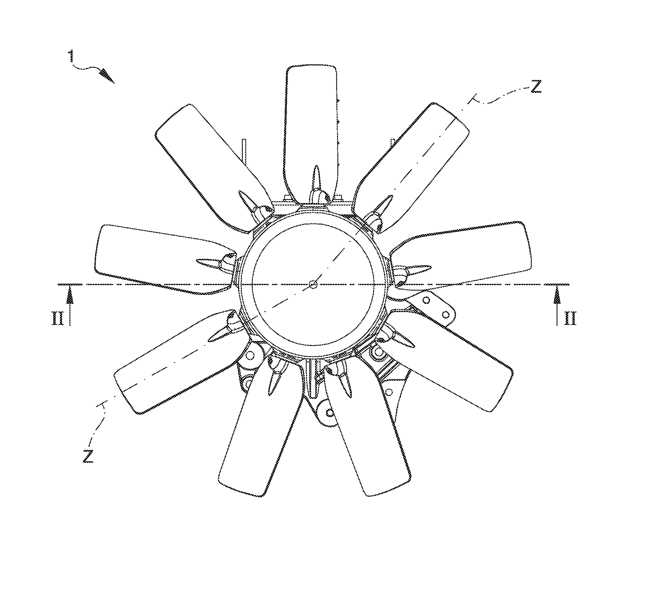
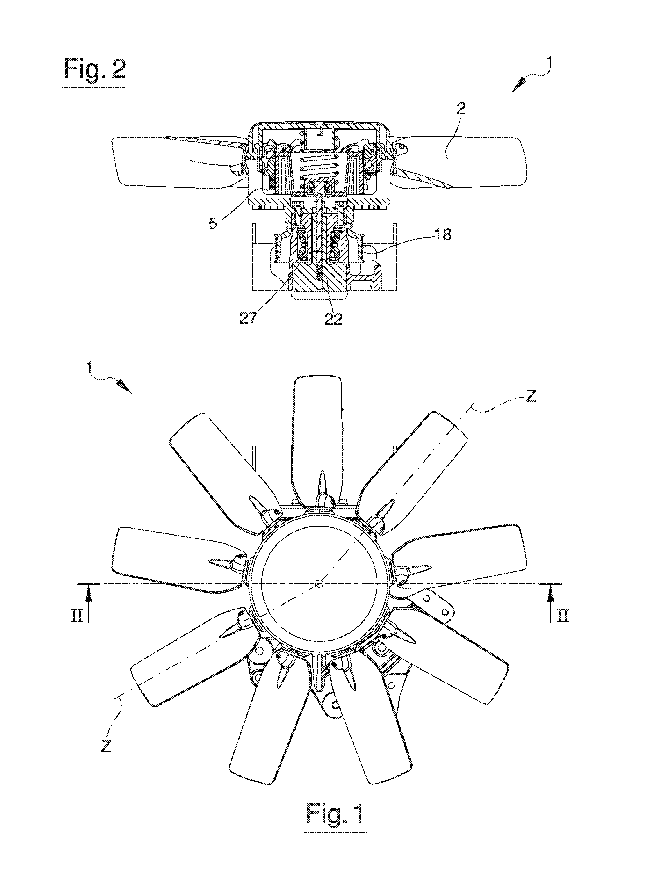
A variable pitch fan is provided, which comprises a plurality of blades (2), a supporting device (3) for supporting the blades (2), a rotation device (18) for rotating the supporting device (3) around a rotation axis (X), so that the blades (2) rotate with the supporting device (3) to control an air flow, and an adjusting device for adjusting a pitch of the blades by tilting each blade (2) around a respective tilt axis (Z), the adjusting device comprising a driven element (4) fixed relative to a blade (2).The adjusting device further comprises a mechanical driving element (5) supported by the supporting device (3) so as to rotate with the supporting device (3), the mechanical driving element (5) being linearly displaceable relative to the supporting device (3) and being coupled to the driven element (4) so that a linear motion of the mechanical driving element (5) is converted into a rotary motion of the driven element (4) around the tilt axis (Z).
Description
FIELD OF THE INVENTION[0001]The invention relates to a variable pitch fan, which may be used in cooling systems, for example for cooling an engine, particularly an engine of an agricultural or industrial machine, such as a tractor. More in general, the variable pitch fan according to the invention may be used to control an air flow, for example in a seeder to blow seeds from a storing tank towards a seeding unit.[0002]The invention further relates to a method for varying a pitch of the blades in a fan.BACKGROUND OF THE INVENTION[0003]Known tractors comprise a suction fan for sucking air from the external environment and directing the air towards the engine so as to cool the latter during operation. The fan comprises a rotatable housing supporting a plurality of blades. Each blade can be rotated around a respective axis so as so vary the blade pitch. By varying the blade pitch, the flow rate of air sucked by the fan can be adjusted according to the engine temperature.[0004]In known t...
Claims
Application Information
Patent Timeline
Application Date:The date an application was filed.
Publication Date:The date a patent or application was officially published.
First Publication Date:The earliest publication date of a patent with the same application number.
Issue Date:Publication date of the patent grant document.
PCT Entry Date:The Entry date of PCT National Phase.
Estimated Expiry Date:The statutory expiry date of a patent right according to the Patent Law, and it is the longest term of protection that the patent right can achieve without the termination of the patent right due to other reasons(Term extension factor has been taken into account ).
Invalid Date:Actual expiry date is based on effective date or publication date of legal transaction data of invalid patent.

