Systems, Devices, and Methods for Calibration of Beam Profilers

a beam profiler and beam technology, applied in the field of beam profiler systems, can solve the problems of inability to readily achieve, high cost, time-consuming, etc., and achieve the effect of compact and inexpensiv

Inactive Publication Date: 2016-01-28
AMO MFG USA INC
View PDF1 Cites 7 Cited by
  • Summary
  • Abstract
  • Description
  • Claims
  • Application Information

AI Technical Summary

Benefits of technology

[0005]There is a need for a tool that can be used for beam profiler focusing and focus verification. Additionally, it may be advantageous if the tool can perform geometrical calibration of a beam profiler in the field without having to remove the beam profiler from the host system. Such a tool may avoid the need for beam profiler removal from a host system and beam profiler shipping to a manufacturer for calibration. In some embodiments, it may be advantageous if the tool is compact and inexpensive and can be used anywhere the beam profiler is installed.

Problems solved by technology

This calibration requirement may be costly, time intensive, or not readily possible if the beam profiler cannot be easily removed from the field or an integrated system.

Method used


Image

  • Systems, Devices, and Methods for Calibration of Beam Profilers
  • Systems, Devices, and Methods for Calibration of Beam Profilers
  • Systems, Devices, and Methods for Calibration of Beam Profilers

Examples


Embodiment Construction

[0051]The subject matter of embodiments of the present invention is described here with specificity, but this description is not necessarily intended to limit the scope of the claims. The claimed subject matter may be embodied in other ways, may include different elements or steps, and may be used in conjunction with other existing or future technologies. This description should not be interpreted as implying any particular order or arrangement among or between various steps or elements except when the order of individual steps or arrangement of elements is explicitly described.

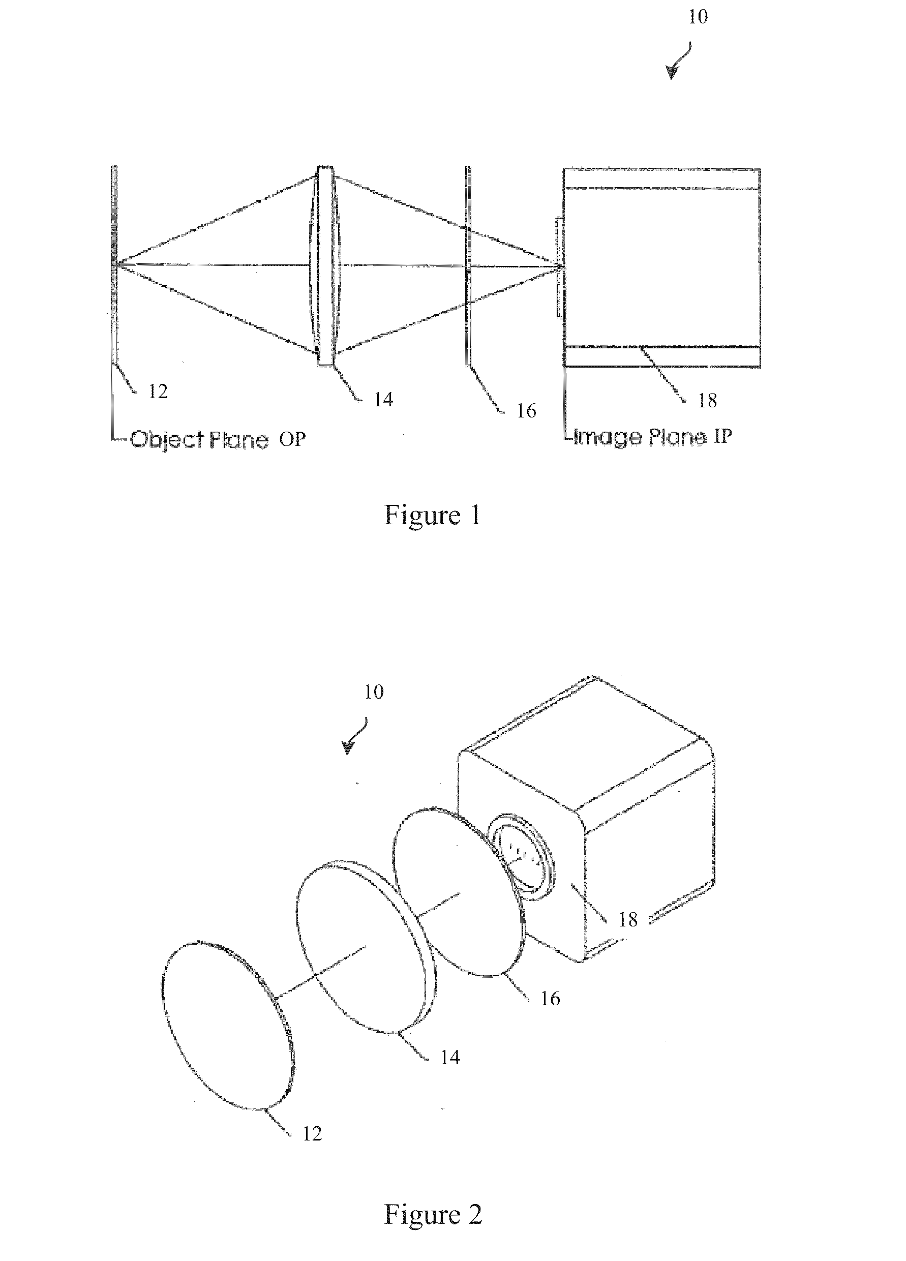
[0052]FIG. 1 shows a side profile of an exemplary UV light beam profiler 10. FIG. 2 shows an isometric view of the exemplary UV light beam profiler 10. UV light beam profiler 10 may include a UV-to-visible light converter 12, objective lens 14, filter 16, and an image sensor (or camera) 18. The components may be housed together in a UV light beam profiler housing (not shown). The objective lens 14 and the fil...


PUM


Abstract

Embodiments generally describe systems, devices, and methods for focusing and calibrating beam profilers. A test object is provided that may include an internal housing rotatable within an external housing. The internal housing may house a light source, a collimator, a filter, and/or a diffuser. A plate may be mounted to the internal housing and may include a plurality of markings. In some embodiments, to focus a beam profiler, the test object may be positioned adjacent the converter plate of a beam profiler. Marker images may be captured and a focus quality may be assessed therefrom. A position of the converter, objective, and/or camera of the beam profiler may be adjusted based on the focus quality. To calibrate, images of the markings in several rotational positions may be captured and used for calibration. The markings may be rotated to several positions by rotating the internal housing relative to the external housing.

Description

CROSS REFERENCE TO RELATED APPLICATIONS[0001]The present application claims the benefit of U.S. Provisional Patent Application No. 62 / 029,164 filed Jul. 25, 2014, the disclosure of which is incorporated herein by reference in its entirety.BACKGROUND OF THE INVENTION[0002]The present invention generally relates to beam profiler systems and more particularly to systems and methods for focusing and geometrically calibrating a beam profiler.[0003]A UV light beam profiler is a metrological imaging tool for determination of geometrical parameters of a beam profile, such as, size, position, uniformity, shape, and others. It may be used in military, medical, and commercial applications where precise control of UV light beam parameters is desired. Like other metrological devices, the beam profiler should be calibrated every time after assembly, repair (e.g., component replacement or the like), alignment, realignment, and for verification sake. This calibration requirement may be costly, time...

Claims


Application Information

Patent Timeline
Patent Type & Authority Applications(United States)
IPC IPC(8): G01J1/04A61F9/008G01J1/16G01J1/42
CPCG01J1/0411G01J1/4257A61F2009/00855A61F9/008G01J1/16G01J1/58G01M11/061G01B11/24G01J1/0488
Inventor BEREZHNYY, IHORTANG, ANTHONYPRICE, HENRY
Owner AMO MFG USA INC
Why Eureka
Try Eureka