Method and apparatus for investigating permittivity in a target domain

Active Publication Date: 2016-01-28
ROCSOLE
View PDF6 Cites 24 Cited by
  • Summary
  • Abstract
  • Description
  • Claims
  • Application Information

AI Technical Summary

Benefits of technology

[0045]Irrespective of the basic geometry and configuration of the conductive background body, the sensor is preferably configured so that when assembled as a part of a process equipment, e.g. as a part of a process pipeline in the case of a tubular sensor, the conductive background body is electrically insulated from the actual process equipment. This reduces coupling of disturbance signals to the measurements.
[0046]In the above, the apparatus according to the present invention is defined via the properties of the sensor only. The device aspect of the present invention can also be implemented as a more complete measurement system implemented as an apparatus comprising, in addition to such s

Problems solved by technology
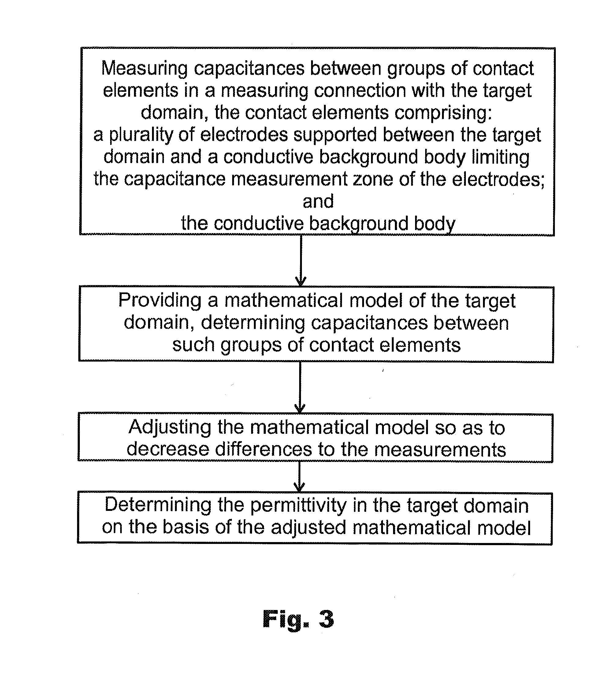
On the other hand, the spatial resolution in reconstructing the permittivit

Method used


Image

  • Method and apparatus for investigating permittivity in a target domain
  • Method and apparatus for investigating permittivity in a target domain
  • Method and apparatus for investigating permittivity in a target domain

Examples


Example

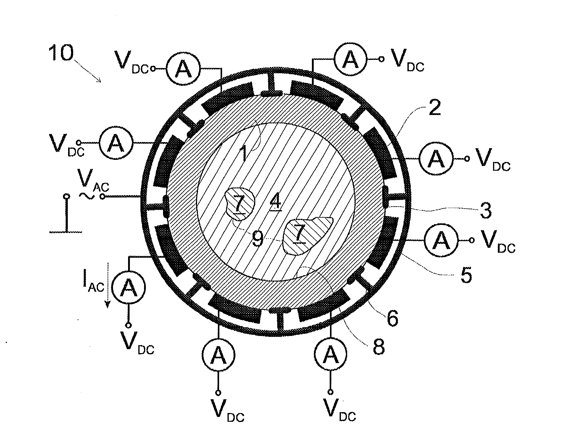
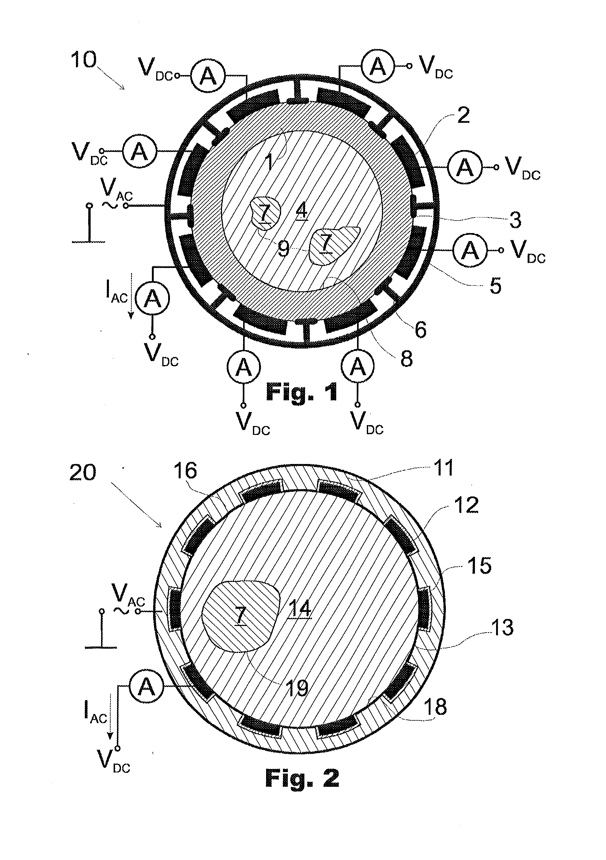
[0058]The sensor 10 of FIG. 1 comprises a section of an electrically insulating pipe 1 forming a support body, on the outer surface of which eight electrodes 2 are attached for performing measurements of one or more capacitance-dependent electrical quantities in a target domain 3 comprising the inner volume of the process pipe 1 as well as the pipe wall. Thus, in the example of FIG. 1, the boundary of the target domain 3 coincides with the outer surface of the pipe 1 and the inner surfaces of the electrodes 2 thereon. Alternatively, the electrodes could lie at least partly embedded in the pipe wall.

[0059]The electrically insulating pipe 1 is surrounded by a cylindrical (tubular) metal sheath 5, comprising flanges 6 extending radially from the sheath to the outer surface of the pipe 1. The metal sheath 5 serves as a screen to isolate the system of the electrodes and the target domain from its surroundings. Further, the flanges 6 extending between the electrodes prevent the adjacent e...


PUM


Abstract

A method for investigating permittivity within a target domain comprises a step of measuring, for a plurality of pairs of contact element groups, the contact elements of the contact element groups being arranged in capacitance measurement connection with the target domain, an electrical quantity of interest proportional to the capacitance of a capacitor formed by a pair of contact element groups; the contact elements comprising a plurality of electrodes supported between the target domain and an electrically conductive background body limiting the capacitance measurement zone of the electrodes. The contact elements may further comprise the electrically conductive background body.

Description

FIELD OF THE INVENTION[0001]The present invention relates generally to methods and apparatuses for monitoring industrial processes by means of non-invasive monitoring techniques, in particular for investigating permittivity in such processes by means of external measurements of capacitances or some other capacitance-dependent electrical quantities of interest. Such techniques are often called electrical capacitance tomography ECT.BACKGROUND OF THE INVENTION[0002]Electrical capacitance tomography ECT is one specific field within the more general field of electrical tomography. ECT as such is a known technique allowing non-invasive monitoring of a target domain on the basis of determination of the permittivity within the target domain.[0003]In general, ECT comprises providing a model of the target domain and the measurement arrangement, making capacitance-related measurements, and adjusting the mathematical model so as to reduce the differences between the simulated and the measured e...

Claims


Application Information

Patent Timeline
IPC IPC(8): G01N27/22
CPCG01N27/22G01N27/24G01N17/008
Inventor LEHIKOINEN, ANSSIVOUTILAINEN, ARTO
Owner ROCSOLE
Why Eureka
Try Eureka