Digital seismic sensor and acquisition device adapted to be connected together via a two-conductor line

a digital seismic sensor and acquisition device technology, applied in seismic signal receivers, seismic instruments, instruments, etc., can solve the problems of sampling clock, phase jitter of data, and inability to allow noise on the line, so as to improve the accuracy of seismic digital sensors

Active Publication Date: 2016-01-28
SERCEL INC
View PDF1 Cites 7 Cited by
  • Summary
  • Abstract
  • Description
  • Claims
  • Application Information

AI Technical Summary

Benefits of technology

[0051]using a local sampling clock, whose drift is compensated as a function of received synchronization information. In other words, we get rid of high performance PLL that extracts the sampling clock from data. Indeed we separate (distinguish) the sampling clock, used by the digital sensing mean (e.g. MEMS-based accelerometer), and the transmission clock, used by the means for receiving and transmitting. This allows to use standard low cost / low quality geophone cable (not being designed to transmit high frequency digital data but low frequency analog data), and to use half-duplex mode on a single pair cable.
[0061]The fact that, according to the particular embodiment of the invention, the local sampling clock and the transmission clock are dissociated allows to use an ADDLL which has many advantages:
[0062]the ADDLL allows to save board space (it has almost a zero size) and is cheaper (it has almost a zero cost) because it is integrated in a CPU included in the digital sensor (this is hardly the case with a PLL);
[0066]Thus the compactness of the seismic digital sensor is further improved.
[0070]means for transmitting, via said two-conductor line, synchronization information providing accurate timing information to enable seismic sensor synchronization.

Problems solved by technology

But in the facts, this is impossible.
Indeed, the noise on the line does not allow it.
More precisely, the phase jitter of the data, and hence of the sampling clock after recovery by the PLL, on this cable would be too high.
In other words, attenuation and distortion induced by such a cable degrade the temporal precision of a clock that would be transmitted on that cable.
Moreover such a cable gets (“picks up”) the ambient electronic noise that would degrade even more this clock.
The Man skilled in the art is faced with another problem: the use of a phase lock loop (PLL), in order to recover the sampling clock coming from the central recording system 1, induces a size which is not compatible with a desired objective of placing the digital sensor in a housing containing usually an analog sensor.
The use of a PLL also induces a great power consumption which is not compatible with a desired objective to reduce the power consumption of the acquisition device.
Thus, the Man skilled in the art has therefore no incentive to pursue the course of trying to combine the concepts of sensor string and digital sensors.

Method used


Image

  • Digital seismic sensor and acquisition device adapted to be connected together via a two-conductor line
  • Digital seismic sensor and acquisition device adapted to be connected together via a two-conductor line
  • Digital seismic sensor and acquisition device adapted to be connected together via a two-conductor line

Examples


Embodiment Construction

[0101]In all of the figures of the present document, identical elements and steps are designated by the same numerical reference sign.

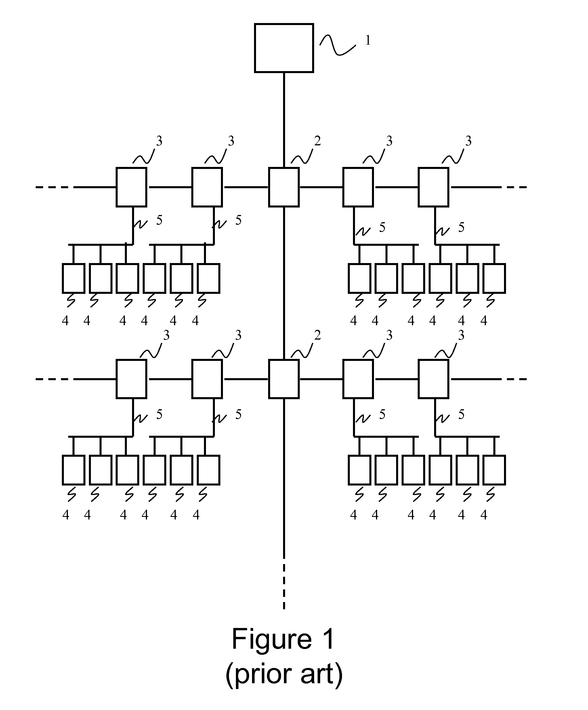
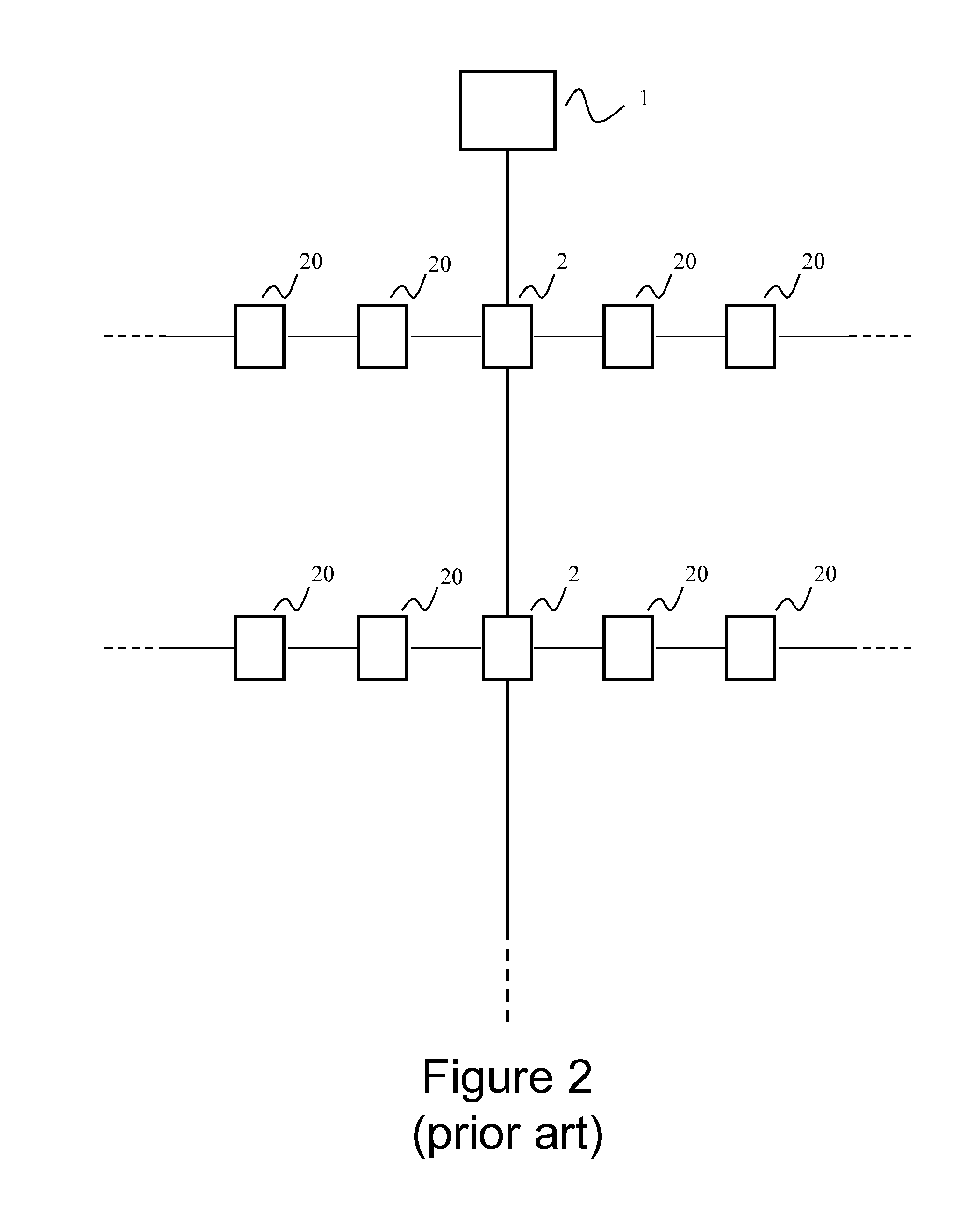
[0102]FIGS. 1, 2 and 6 relate to prior art and have already been discussed above.

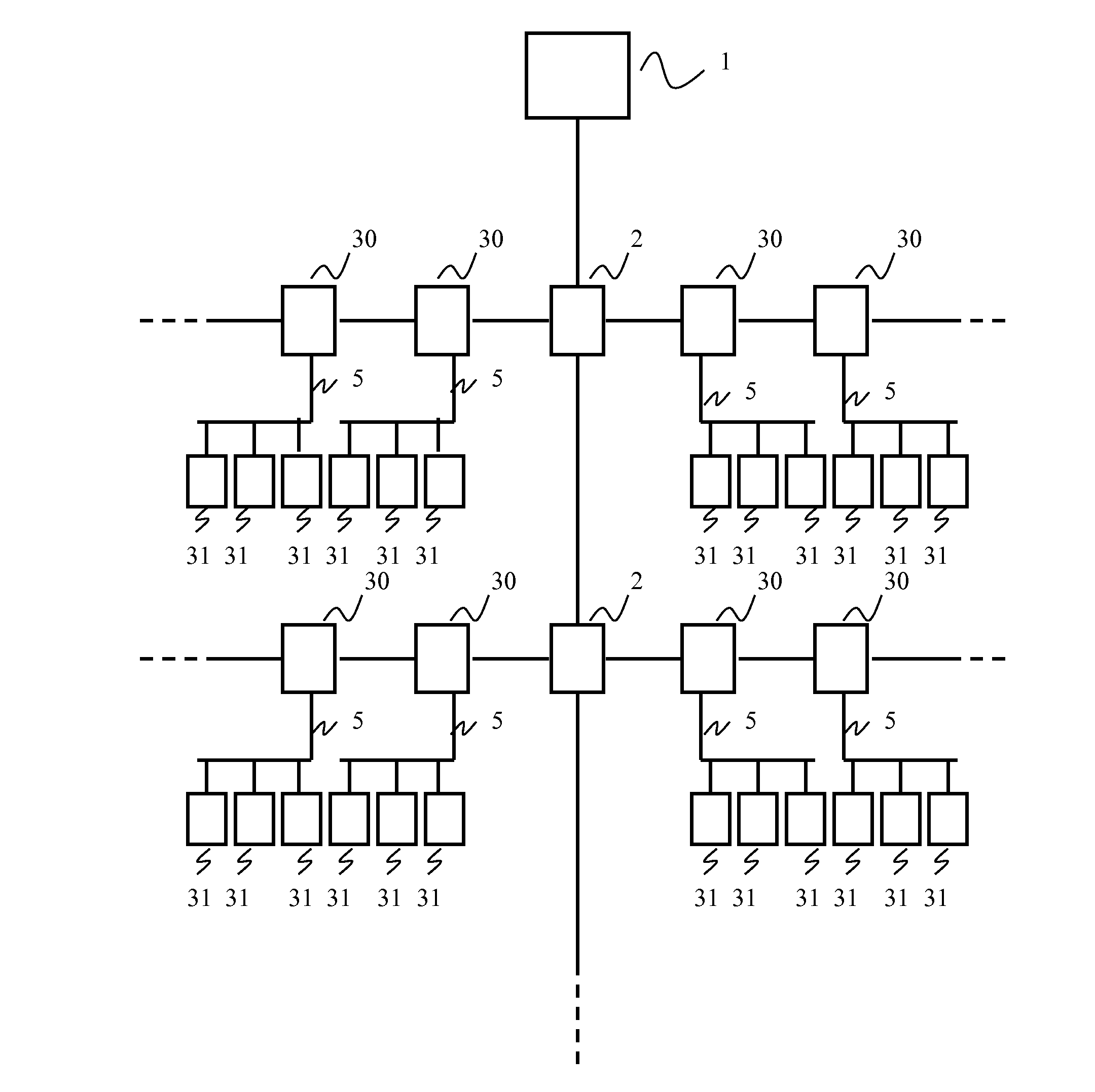
[0103]Referring now to FIG. 3, we present a seismic data acquisition system according to a particular embodiment of the invention.

[0104]As in FIGS. 1 and 2, the seismic data acquisition system comprises a central recording system 1 (usually onboard a recording truck) and intermediate collection devices 2 (“concentrator devices”).

[0105]As in FIG. 1, the system also comprises strings of sensors, but in FIG. 3 the sensors used are new digital sensors 31 (see description of FIG. 4 below).

[0106]For a best understanding of the present invention, each reference 31 designates a digital sensor and its corresponding housing and casing.

[0107]Each string of digital sensors 31 is connected, via a two-conductor line 5, to a new acquisition device 30, also referred to below as “new Digi...


PUM


Abstract

A digital seismic sensor adapted to be connected, via a two-conductor line, to an acquisition device. The digital seismic sensor includes: a digital sensor; a local sampling clock providing a sampling frequency; a receiver for receiving command data coming from the acquisition device and synchronization information providing accurate timing information to enable seismic sensor synchronization; a compensator for compensating, as a function of the synchronization information, a drift of the local sampling clock; a transmitter for transmitting seismic data towards the acquisition device; a driver for driving the receiver and the transmitter, according to a half-duplex transmission protocol over the two-conductor line and using a transmission clock extracted from the received command data; a power receiver for receiving electrical power; and a coupler for coupling the command and synchronization information receiver, the transmitter and the power receiver to the two-conductor line.

Description

1. CROSS-REFERENCE TO RELATED APPLICATIONS[0001]This application is a continuation of U.S. application Ser. No. 13 / 921,827 filed on Jun. 19, 2013, which claims the benefit of EP Patent Application No. 12172569.1 filed on June 19, 2012, the contents of which are hereby incorporated by reference in their entirety.2. STATEMENT REGARDING FEDERALLY SPONSORED RESEARCH OR DEVELOPMENT[0002]None.3. THE NAMES OF PARTIES TO A JOINT RESEARCH AGREEMENT[0003]None.4. FIELD OF THE INVENTION[0004]The field of the invention is that of seismic data acquisition. More specifically, particular embodiments of the invention relate to a digital seismic sensor and an acquisition device adapted to be connected together via a two conductor line. A particular application of the invention relates to land seismic data acquisition systems.[0005]These embodiments of the invention can be applied in particular in the industry of oil exploration by seismic method, but may be applied to any field implementing a seismic...

Claims


Application Information

Patent Timeline
Patent Type & Authority Applications(United States)
IPC IPC(8): G01V1/22G01V1/20
CPCG01V1/20G01V1/22G01V1/3808
Inventor PENNEC, DANIELLAINE, JEROMEHAMON, JACQUES
Owner SERCEL INC
Why Eureka
Try Eureka