Method and apparatus for head worn display with multiple exit pupils

a head-worn display and pupil technology, applied in the field of head-worn displays, can solve the problems of increasing the so-called eyebox of the display, affecting the use of the display, so as to reduce the power consumption of the devi

Active Publication Date: 2016-02-04
GOOGLE LLC
View PDF18 Cites 320 Cited by
  • Summary
  • Abstract
  • Description
  • Claims
  • Application Information

AI Technical Summary

Benefits of technology

[0039]In a further preferred embodiment the method for displaying an image viewable by an eye further comprises deactivating selected ones of the plurality of light beams associated to each of the exit pupils, in correspondence to the eye's position at a given moment, whereby eye tracking information is used to deactivate misaligned exit pupils to reduce device power consumption.

Problems solved by technology

While projection technology is advancing, there is still currently a difficult trade-off between field of view and the bulk and weight in see-through HWDs.
In most cases a significant field of view (>30-40 degrees) requires bulky optics making their usage difficult for many applications.
Smaller field of view systems have been introduced with more acceptable form-factors, but the challenge remains to create useful implementations of see-through displays with aesthetically pleasing form factors for a wide range of applications and even everyday use.
One primary challenge in the design of HWDs is the expansion of the so-called eyebox of the display.
However this usually leads to a more bulky optical system.
The drawback of this approach is that the beam expansion optics creates added optical bulk with trade-offs similar to other conventional HWD approaches.
These systems relied on eye tracking and did not use a method to unify the images produced by the multiple exit pupils.
This creates a larger aperture, “faster” optical system, which is more difficult to control in terms of aberrations.

Method used


Image

  • Method and apparatus for head worn display with multiple exit pupils
  • Method and apparatus for head worn display with multiple exit pupils
  • Method and apparatus for head worn display with multiple exit pupils

Examples


Embodiment Construction

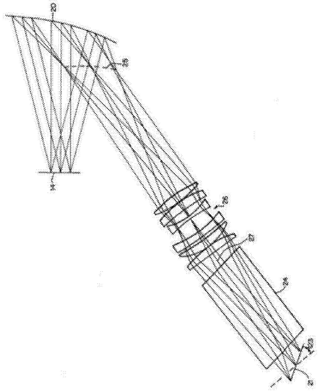
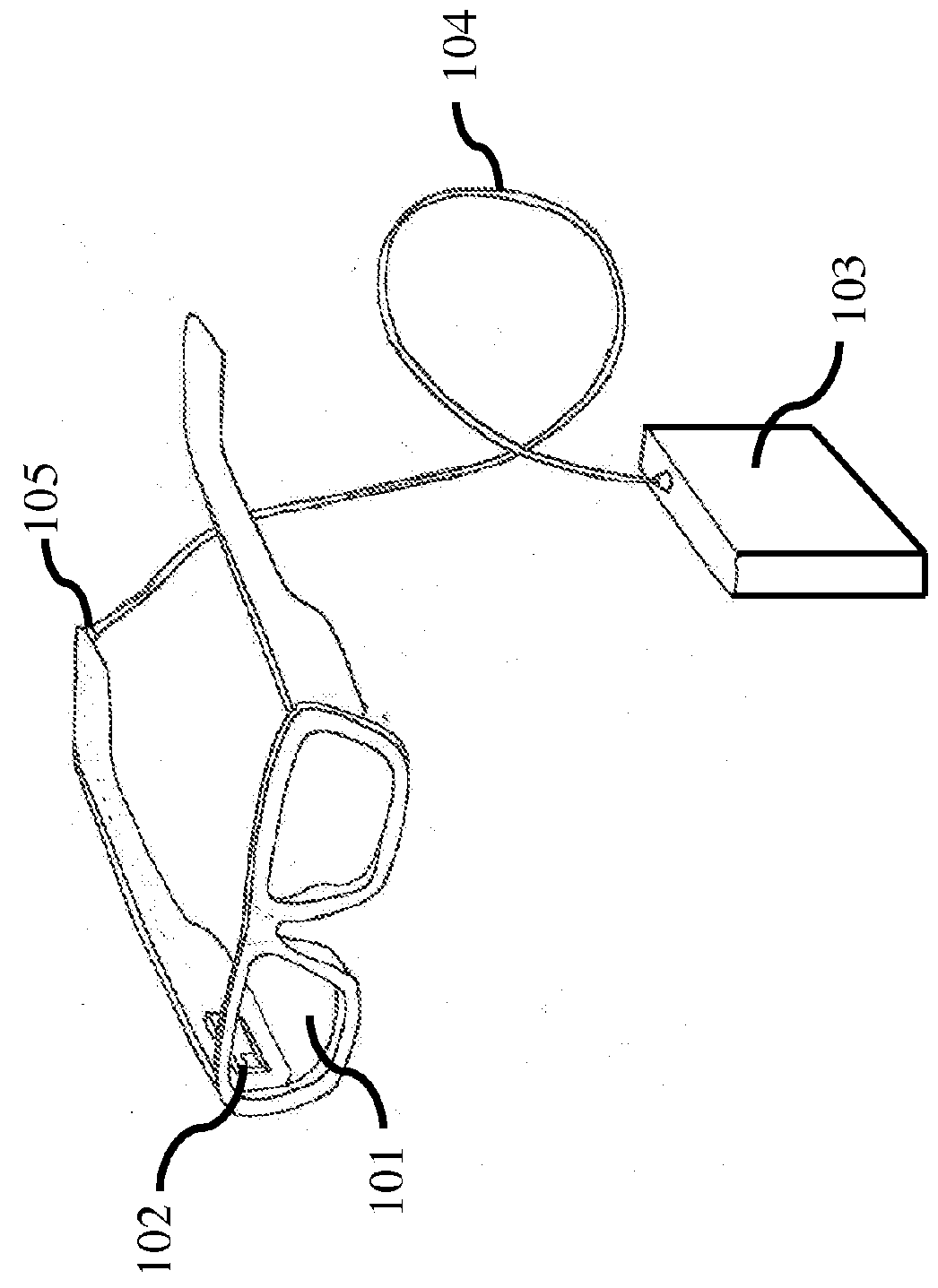
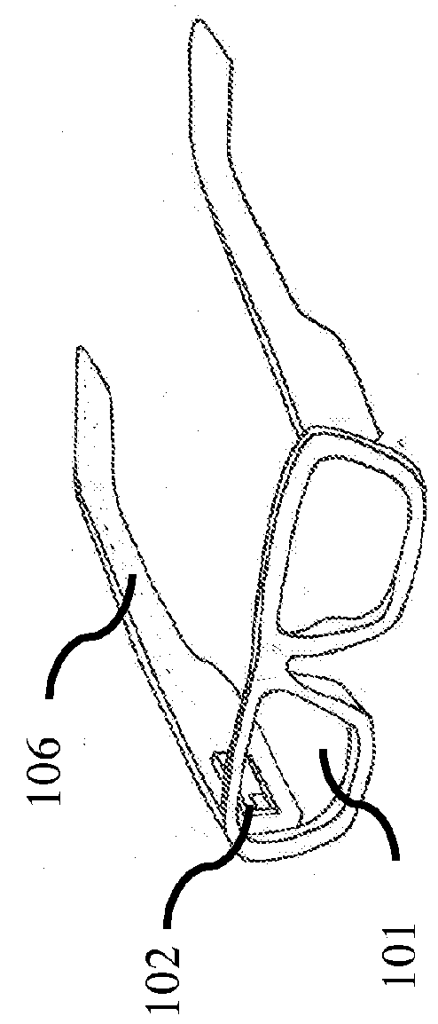
[0163]The techniques, apparatus, materials and systems as described in this specification can be used to implement a HWD based on a scanning projector and holographic transflector, and can also be applied to head-up displays (HUDs)—see through display systems placed at a larger distance from the eye.

[0164]In at least one embodiment of the invention a head worn display creates a scanned image directly on the user's retina using a scanning mirror projector. The exit pupil of the scanning mirror is placed at the entrance pupil of the eye using a transflector element, which can be, but is not limited to a holographic optical element (HOE). In addition to reflecting the display light toward the eye, the transflector also acts to efficiently transmit light from the environment to the eye, allowing for the display to be added to natural vision. This is often referred to as “augmented reality” or sometimes “mixed reality”. Additionally, the described invention allows for an effectively expa...


PUM


Abstract

A method for displaying an image viewable by an eye, the image being projected from a portable head worn display, comprises steps of: emitting a plurality of light beams of wavelengths that differ amongst the light beams; directing the plurality of light beams to a scanning mirror; modulating in intensity each one of the plurality of light beams in accordance with intensity information provided from the image, whereby the intensity is representative of a pixel value within the image; scanning the plurality of light beams in two distinct axes with the scanning mirror to form the image; and redirecting the plurality of light beams to the eye using a holographic optical element acting as a reflector of the light beams, whereby the redirecting is dependent on the wavelength of the light beam, to create for each light beam an exit pupil at the eye that is spatially separated from the exit pupils of the other light beams.

Description

FIELD OF THE INVENTION[0001]The present invention relates to head-worn displays (HWDs), in particular, those systems that give the possibility to superimpose virtual images onto normal vision using eyewear with built in display capability.BACKGROUND[0002]The large-scale adoption of consumer mobile computing devices such as smartphones offers new possibilities for human interaction with computers and as well as the surrounding environment. Next generation mobile devices are expected to provide information by displaying it in a different manner than the current hand portable display screen. Advances in projection display technologies are enabling near the eye displays, such as a pair of see through glasses with overlaid information displayed directly to the user.[0003]See-through displays have been used for decades for defense applications. For example, Jet fighter pilots have been using heads-up displays (HUDs) in aircraft and helmet-mounted displays (HMDs) to provide navigational an...

Claims


Application Information

Patent Timeline
Patent Type & Authority Applications(United States)
IPC IPC(8): G02B27/01G02B5/18
CPCG02B27/0172G02B5/189G02B5/188G02B2027/0174G02B2027/0178G02B2027/0125G02B2027/011G02B2027/014G02B2027/0112
Inventor TREMBLAY, ERICGUILLAUMEE, MICKAELMOSER, CHRISTOPHE
Owner GOOGLE LLC
Why Eureka
Try Eureka