Ultrasonic device and probe as well as electronic apparatus and ultrasonic imaging apparatus
- Summary
- Abstract
- Description
- Claims
- Application Information
AI Technical Summary
Benefits of technology
Problems solved by technology
Method used
Image

Examples
first embodiment
(2) Structure of Ultrasonic Device
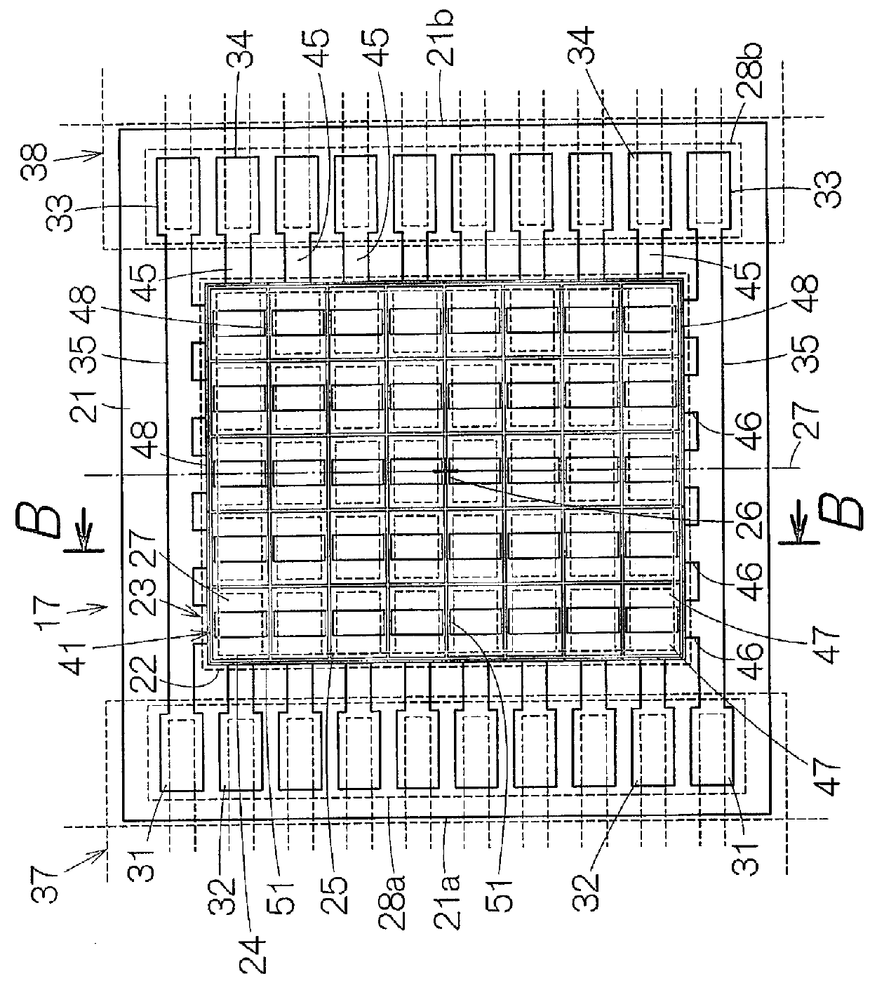
[0030]FIG. 2 schematically shows a plan view of the ultrasonic device 17 according to a first embodiment. The ultrasonic device 17 includes a base 21. An element array 22 is formed on a surface (first surface) of the base 21. The element, array 22 is constituted by an arrangement of thin-film ultrasonic transducer elements (hereinafter referred to as “elements”) 23 that are arranged in an array. The arrangement is in the form of a matrix having a plurality of columns and a plurality of rows. The arrangement may also be established as a staggered arrangement. In a staggered arrangement, a group of elements 23 in each even row can be displaced relative to a group of elements 23 in each odd row by one-half of the column pitch. Either the number of elements in each odd row or the number of elements in each even row may be smaller than the other by one.
[0031]Each element 23 includes a vibration film 24. Details of the vibration film 24 will be described ...
second embodiment
(4) Structure of Ultrasonic Device
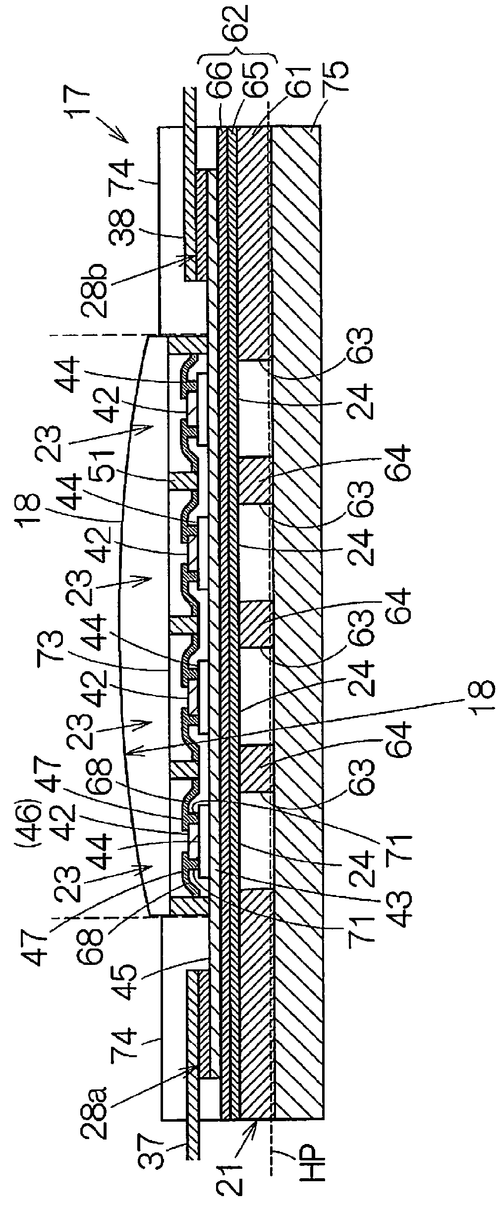
[0057]FIG. 5 corresponds to FIG. 3 and schematically shows an enlarged cross-sectional view of an ultrasonic device 17a according to a second embodiment. In the ultrasonic device 17a, a cavity 76 is formed in each wall 51. The cavity 76 extends from a top surface 51a of the wall 51 that is farthest from the base 21 with respect to the height direction toward the base 21. However, the cavity 76 ends at an intermediate position without reaching an interface of the wall 51. That is to say, the cavity 76 opens in the top surface 51a of the wall 51, and the bottom of the cavity 76 is located at a predetermined height position from the first protective film 47 with respect to the height direction. Otherwise, the ultrasonic device 17a has the same configuration as the ultrasonic device 17 according to the above-described first embodiment.
[0058]The acoustic impedance of the material for the walls 51 differs from the acoustic impedance of the space within th...
third embodiment
(5) Structure of Ultrasonic Device
[0060]FIG. 6 schematically shows a plan view of an ultrasonic device 17b according to a third embodiment. In the ultrasonic device 17b, an interconnect pattern (interconnect) 77 made of an electrically conductive material is formed in the row direction of the arrangement of the element array 22 in parallel with the first electric conductors 45. The interconnect pattern 77 is disposed outside the regions of the vibration films 24. The interconnect pattern 77 is spatially separated from the first electric conductors 45. That is to say, the interconnect pattern 77 is electrically isolated from the first electric conductors 45. The interconnect pattern 77 may be formed of an electrically conductive material such as gold, for example. The two ends of the interconnect pattern 77 are respectively connected to top electrode terminals 78. The top electrode terminals 78 are individually arranged between two bottom electrode terminals 32 in the first terminal ...
PUM
 Abstract
Description
Claims
Application Information
 - R&D
- Intellectual Property
- Life Sciences
- Materials
- Tech Scout
- Unparalleled Data Quality
- Higher Quality Content
- 60% Fewer Hallucinations
Browse by: Latest US Patents, China's latest patents, Technical Efficacy Thesaurus, Application Domain, Technology Topic, Popular Technical Reports.
© 2025 PatSnap. All rights reserved.Legal|Privacy policy|Modern Slavery Act Transparency Statement|Sitemap|About US| Contact US: help@patsnap.com