Catheter assembly with segmented stabilization system

a catheter and stabilization system technology, applied in the field of catheters, can solve the problems of difficult finding substandard veins, many wasted devices, and difficulty in procedures, and achieve the effect of reducing the likelihood of repeated vein punctures for patients and associated effects

Active Publication Date: 2016-02-18
TELEFLEX LIFE SCI LTD
View PDF6 Cites 51 Cited by
  • Summary
  • Abstract
  • Description
  • Claims
  • Application Information

AI Technical Summary

Benefits of technology

[0009]b. deters misplacement, puncturing, or other damage to blood vessels including peripheral veins and arteries;
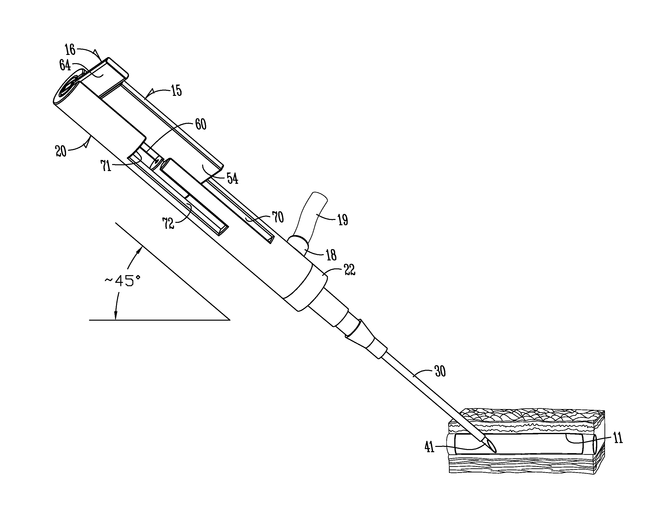
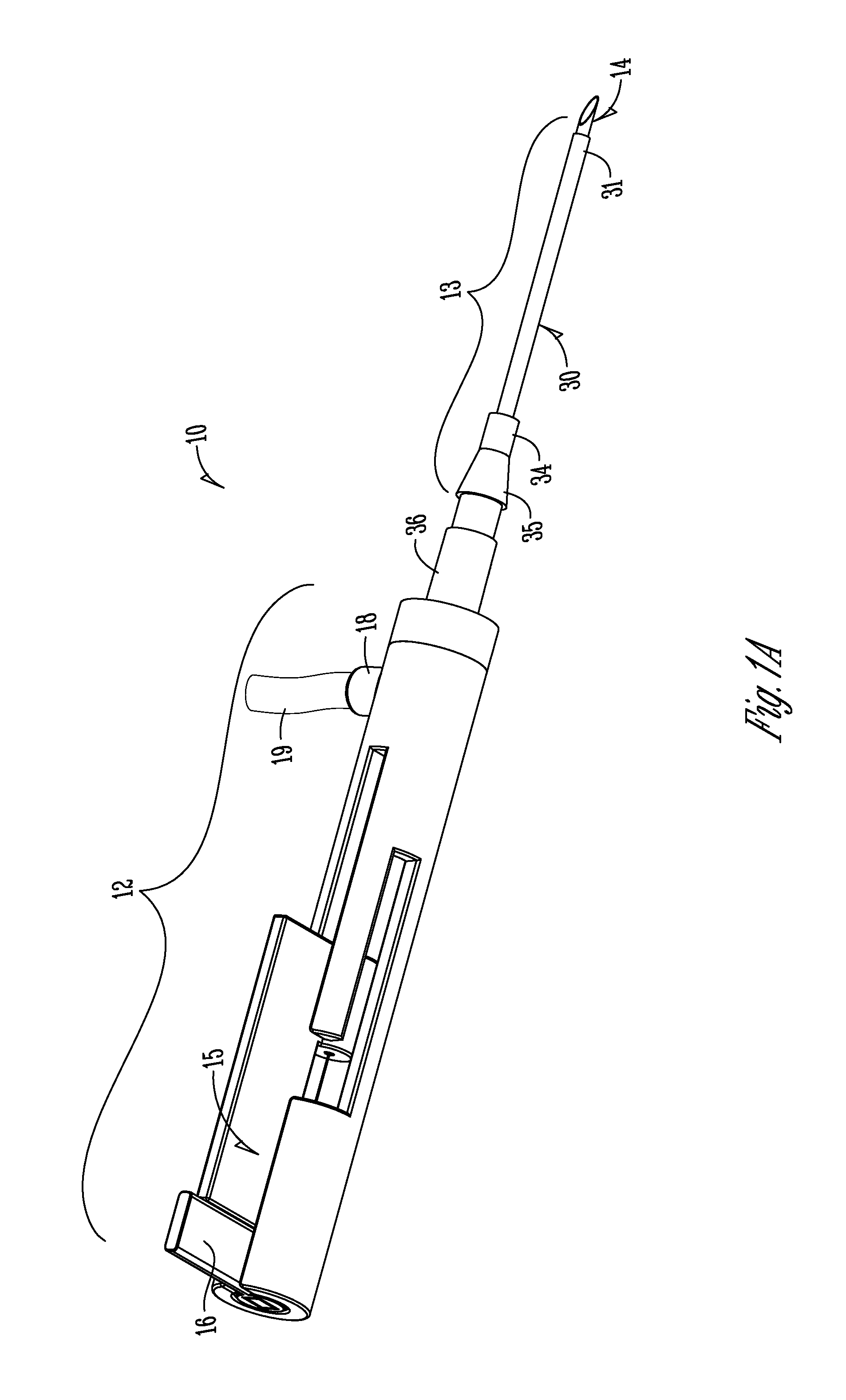
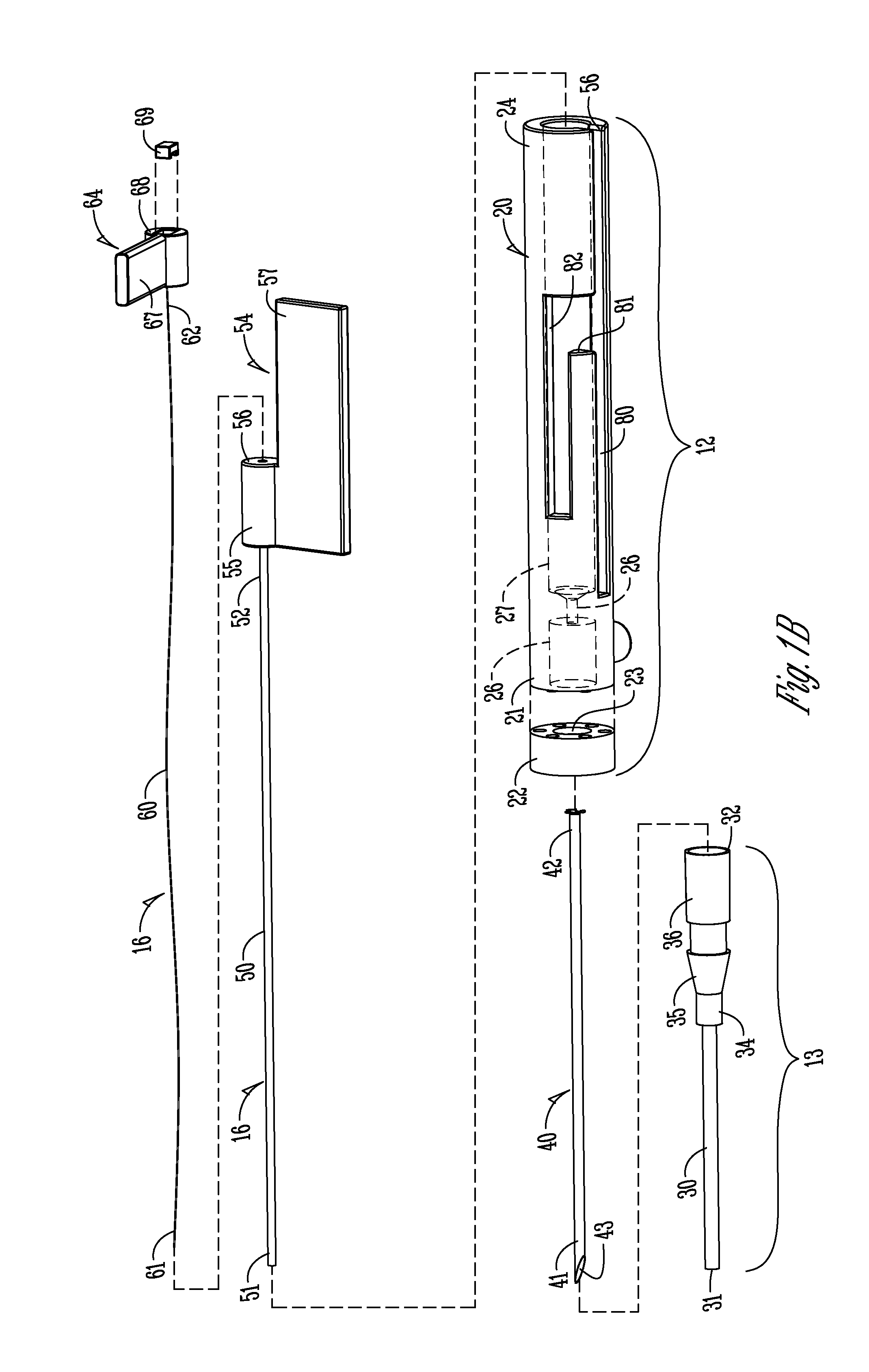
[0029]An example of the guide would be a slot arrangement or system in the body / handle. In one example, the controls and guiding structure in the actuator handle comprise essentially a key and slot arrangement. The first step deployment allows a single pushing forward of sliders (keys) along a first slot basically aligned with the longitudinal axis of the needle. A transitional slot transverse to that first slot would allow a second slider to be moved to a second spaced apart but parallel slot that extends farther distally to allow the second step deployment of just the guiding element. The slot arrangement can allow the actuating body or handle to be held in one hand, and a thumb or finger of the user control both steps with that one hand with high assurance of the correct order of deployment. It can also give tactile feedback regarding whether each or any of the components being introduced through the skin is deemed to be moving to the desired location inside the patient's body.

Problems solved by technology

Many of these devices are wasted due to failure to properly cannulate or thread the catheter into the vein.
Furthermore, the procedure varies in difficulty depending on the condition of the patient.
Such substandard veins are difficult to find, and maneuvering a needle within them is arduous.
First, vein, as compared to arterial, walls are thin, only a few cells thick at points, and the force used to maneuver the guide wire may result in puncturing both sides of the vein, thus wasting the catheter and destroying usefulness of the vein distal to the attempt site for catheterization.
Such a guide wire used in a peripheral intravenous catheter may not be flexible enough to effectively maneuver within a vein.
Finally, difficulties arise in administering any intravenous catheter or guide wire due to failure to easily locate the veins due to their flexible structure.
As veins move in response to pressure exerted near them, multiple attempts to properly insert the catheter may be necessary, which in turn provides further pain and discomfort to the patient.
Because of these barriers, few devices have successfully been able to cannulate thin and winding veins as well as such arteries.
Analogous issues can exist in other catheterizations or placement of cannula or sheaths.
This requires a specific skill set and the overhead and added complexity of such sometimes costly equipment.
It is particularly difficult with infants, children, the obese, or the ill.
It can result in blown veins or arteries.
Therefore, the sheer numbers and failed attempts can result in expenditure of resources such as discarding incorrectly placed catheters as well as health professional's time.

Method used


Image

  • Catheter assembly with segmented stabilization system
  • Catheter assembly with segmented stabilization system
  • Catheter assembly with segmented stabilization system

Examples


exemplary embodiment three

[0116]FIGS. 9A and B show, in similar form to FIGS. 8A and 8B, a further alternative embodiment 10″ of the invention. It functions essentially like the embodiment of FIGS. 8A and 8B with the following additional feature.

[0117]This embodiment shows that further deployable and retractable members are possible. In one example, an additional slider 44′ could be connected to some other type of sheath or cannula that could be slid over hollow stabilizing component 50′ and selectively moved forwardly or distally. It could simply be a catheter sheath.

[0118]However, an alternative possibility exists. Second U-shaped slider 44′ could be connected to a carriage that slides in the same slot / bore as the carriage portions of slider 64′ and 54′ of FIG. 9A. Slider 44′ could have puncture needle 40′ fixed to it. Thus, the additional feature of this embodiment is that needle 40′ could be independently moved forward relative to handle 20′. Slider 54′ (U-shaped) can also. Slider 44′ can provide a mecha...


PUM


Abstract

A catheter assembly with segmented or step-wise deployment stabilization system includes a base or handle, puncture needle extending from the handle, and a deployment mechanism or mechanisms to selectively extend from the distal end of the needle for first length a hollow stabilizing component and as a second step to a second further length a stabilizing guide wire element. The needle will gain sub-dermal access to the patient to the intended position for deployment of a catheter. Hollow stabilizing component provides for a first additional guide and support for a catheter sheath from the distal end of the needle. The stabilizing wire element provides additional length, guide and support for the catheter sheath. The hollow stabilizing component has some degree of flexibility as does the guide wire to minimize chance of damage to surrounding tissue. The user can feel resistance and have the opportunity to retract either component and attempt redeployment without a retraction of the puncture needle and a second poke of the patient's skin. In the example for peripheral venous catheterization, the system reduces the probability of blood vessel puncture. The deployment mechanism can have a guiding system which ensures the proper sequence of deployment.

Description

CROSS-REFERENCE TO RELATED APPLICATIONS[0001]This application claims priority under 35 U.S.C. §119 to provisional application Ser. No. 61 / 808,982 filed Apr. 5, 2013, herein incorporated by reference in its entirety.FIELD OF INVENTION[0002]The present invention relates generally to the field of catheters and methods of using the same. More particularly, but not exclusively, it is a method for facilitating the insertion of a peripheral intravascular catheter into a vein or artery by using a hollow stabilizing component through which another component, one example being a thin guide wire, is passed. Subsequently, the method allows for a catheter sheath to pass over the hollow stabilizing component and any additional components such as a thin guide wire, emplacing the catheter within the patient's vessel.RELATED ART[0003]Peripheral intravascular catheters are ubiquitous in hospitals and medical centers throughout the world. Many of these devices are wasted due to failure to properly can...

Claims


Application Information

Patent Timeline
Patent Type & Authority Applications(United States)
IPC IPC(8): A61M25/06A61M25/09
CPCA61M25/0606A61M25/0662A61B17/3403A61M2025/0681A61M25/09
Inventor GALGANO, JOSHUA J.KIM, JR., HANJUNANDERSON, ROBERT J.
Owner TELEFLEX LIFE SCI LTD
Why Eureka
Try Eureka