Power meter with two detector elements for a power measurement even of extremely low frequencies

a technology of detector elements and power meters, which is applied in the direction of moving-iron instruments, instruments, electrical testing, etc., can solve the problems of inability to detect the electrical power of low-frequency signals, the inability to measure the time variation of envelope power, and the lengthening of measurement times

Active Publication Date: 2016-02-18
ROHDE & SCHWARZ GMBH & CO KG
View PDF2 Cites 2 Cited by
  • Summary
  • Abstract
  • Description
  • Claims
  • Application Information

AI Technical Summary

Benefits of technology

[0028]This embodiment according to another aspect of the invention has the advantage that, through the frequency-dependent embodiment o

Problems solved by technology

The detector element accordingly has a high-pass behaviour, which makes the detection of electrical powers of low-frequency signals impossible.
With such large time constants τ,

Method used


Image

  • Power meter with two detector elements for a power measurement even of extremely low frequencies
  • Power meter with two detector elements for a power measurement even of extremely low frequencies
  • Power meter with two detector elements for a power measurement even of extremely low frequencies

Examples


Embodiment Construction

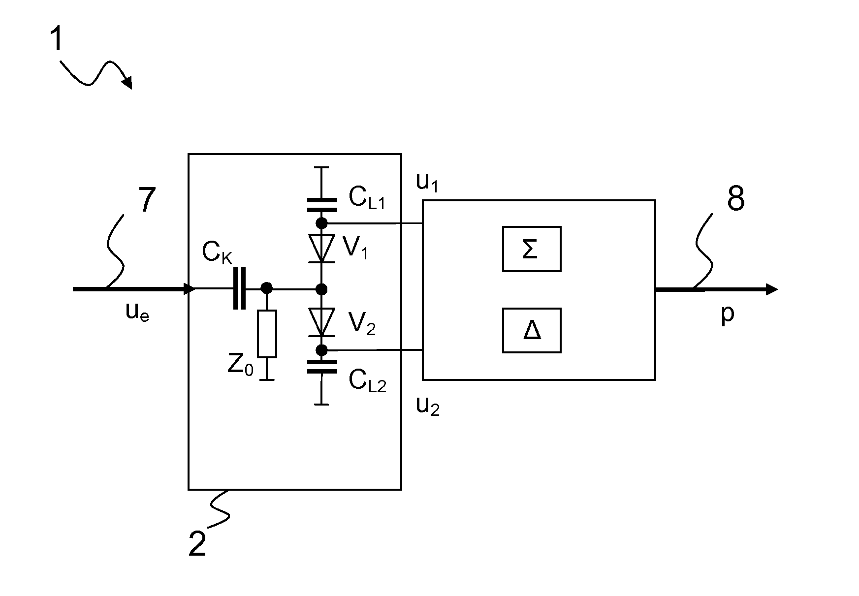
[0042]FIG. 1 shows a simplified functional circuit diagram of an ideal power sensor according to the current internal status in the applicant's laboratory. An ideal power meter absorbs and measures the power p supplied as a whole to a measurement input. The supplied power p is the power sum of all partial signals, that is, for example, the sum of the measurement signal 7, its harmonic and the superposed broadband noise, from all spectral lines of the input signal respectively.

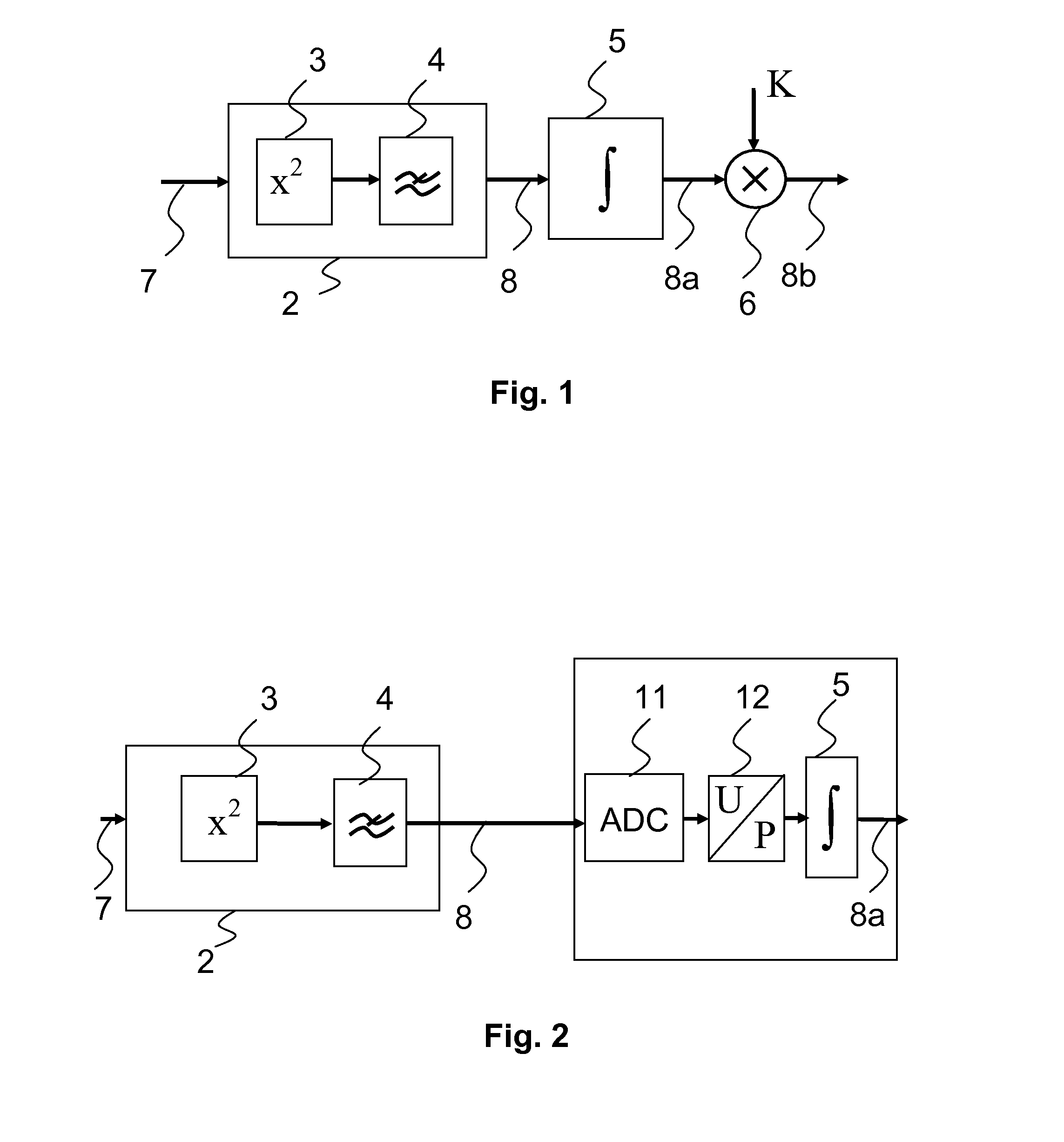
[0043]The measurement signal 7 is generally an electrical voltage u or an electrical current i or—as is conventional in high-frequency technology and microwave technology —a wave. In the power meter 1, a power detector 2 is used to detect the supplied power p. All measurement principles for the detection of the electrical power p can be represented mathematically by a squaring 3 of the applied alternating signal 7. The output signal of the squaring unit 3 is a value proportional to the momentary electrical powe...


PUM


Abstract

The invention relates to a power meter with a two-path or multipath detector comprising at least two detector elements. Each detector element generates an output voltage. In order to detect an electrical power of an alternating electrical input signal, the sum and the difference of the output voltages of the detector elements are formed separately from one another.

Description

PRIORITY[0001]This application claims priority of German patent applications DE 10 2014 215 924.5 filed on Aug. 12, 2014 and DE 10 2015 203 649.9 filed on Mar. 2, 2015, which are incorporated by reference herewith.FIELD OF THE INVENTION[0002]The invention relates to an extension of the frequency range of a power meter to the DC voltage in order to measure the power of high-frequency or respectively microwave signals.BACKGROUND OF THE INVENTION[0003]Within a power meter, a power detector, for example, is used. The measurement value derived from an applied alternating signal—the measurement signal—is obtained either from the heat resulting from absorption or by squaring the signal voltage and subsequent averaging. In general, the measurement signal is an electrical voltage or an electrical current; however, in principle, it could also be any other physical parameter.[0004]In the case of the diode-based power sensors, a squaring of the signal voltage is achieved on the basis of the non...

Claims


Application Information

Patent Timeline
IPC IPC(8): G01R21/133
CPCG01R21/133G01R19/10
Inventor PERNDL, WERNERKUNZE, ALEXANDERKUEFNER, BURKHARDREICHEL, THOMAS
Owner ROHDE & SCHWARZ GMBH & CO KG
Why Eureka
Try Eureka