System and method for optimizing composite laminate structures

a composite laminate and optimization system technology, applied in the direction of electric controllers, mechanical control devices, instruments, etc., can solve the problems of reducing user friendliness, composite laminate structures, and more difficult to find global optimum design solutions, so as to overcome the time-consuming and costly nature of existing problems

Active Publication Date: 2016-02-25
THE BOEING CO
View PDF10 Cites 9 Cited by
  • Summary
  • Abstract
  • Description
  • Claims
  • Application Information

AI Technical Summary

Benefits of technology

[0009]Example implementations of the present disclosure provide an improved system and method for optimizing composite laminate structures to overcome the time-consuming and costly nature of existing solutions

Problems solved by technology

However, composite laminate structures having additional design variables, such as fiber orientation and ply thickness, may be more challenging to find a global optimum design solution.
The use of such finite element modeling software utilizing a finite element model (FEM) for composite laminate optimization may have decreased user friendliness, and may require precision, such as with element size and meshing, to achieve an accurate FEM analysis, which, in turn, may increase time and cost of design

Method used


Image

  • System and method for optimizing composite laminate structures
  • System and method for optimizing composite laminate structures
  • System and method for optimizing composite laminate structures

Examples


Embodiment Construction

[0031]Disclosed embodiments will now be described more fully hereinafter with reference to the accompanying drawings, in which some, but not all of the disclosed embodiments are shown. Indeed, several different embodiments may be provided and should not be construed as limited to the embodiments set forth herein. Rather, these embodiments are provided so that this disclosure will be thorough and fully convey the scope of the disclosure to those skilled in the art.

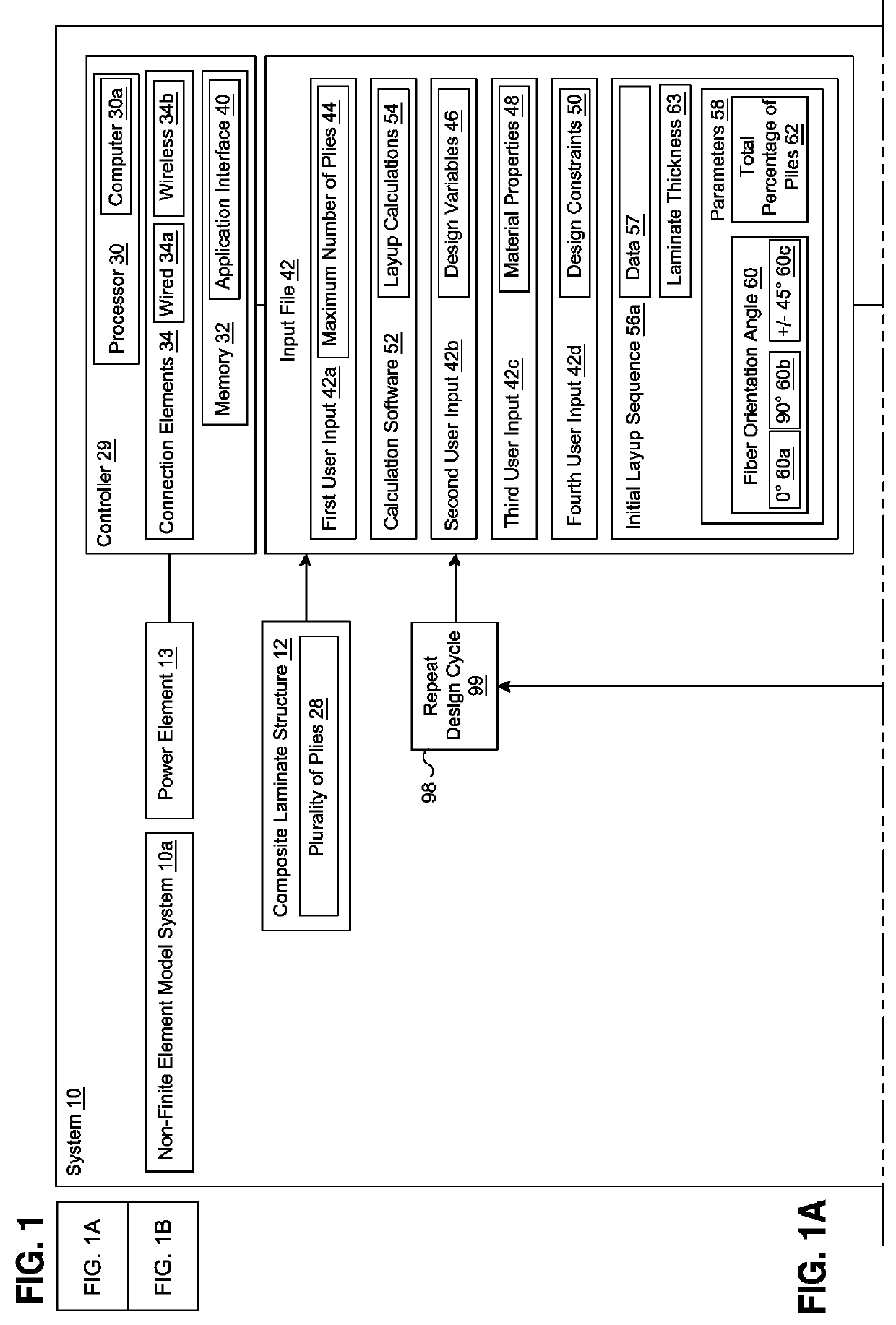
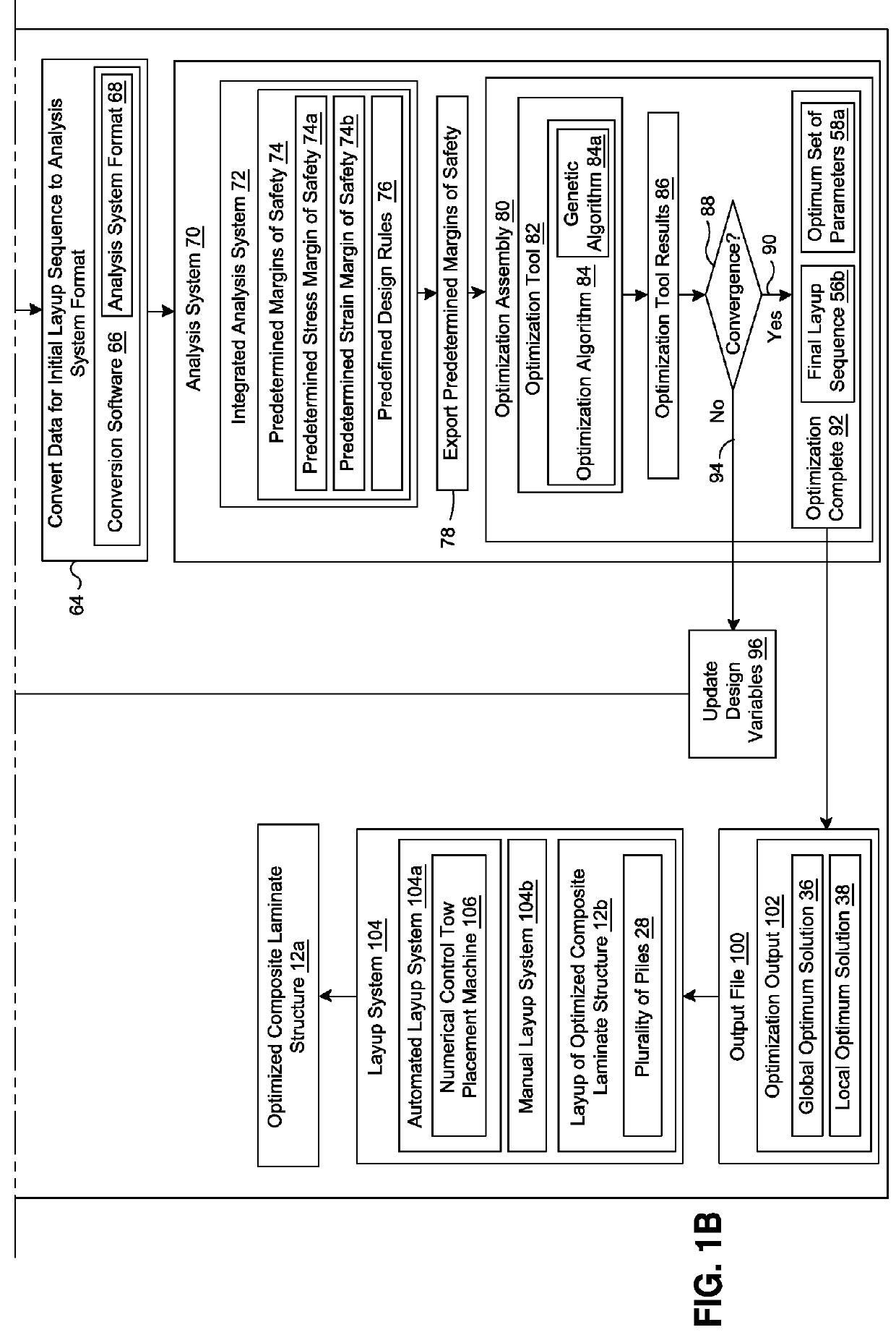
[0032]FIG. 1, which includes FIG. 1A and FIG. 1B, is an illustration of a system flow diagram showing an embodiment of the system 10 of the disclosure. In one embodiment of the disclosure, there is provided the system 10 (see FIG. 1 (FIG. 1A)) for creating for a composite laminate structure 12 (seeFIG. 1 (FIG. 1A)) an optimized composite laminate structure 12a (see FIG. 1 (FIG. 1B)) containing a plurality of plies 28 (see FIG. 1 (FIG. 1A)). The system 10 (see FIG. 1 (FIG. 1A)) is preferably a non-finite element model (non-F...


PUM

PropertyMeasurementUnit
Fractionaaaaaaaaaa
Fractionaaaaaaaaaa
Fractionaaaaaaaaaa

Abstract

A system and method for creating an optimized composite laminate structure containing a plurality of plies. The system has a processor and a memory, including an application interface. The application interface, when executed by the processor, is configured to operably: receive an input file having one or more of a maximum number of plies, design variables, material properties, and design constraints; determine an initial layup sequence defining parameters of a fiber orientation angle for each ply, and a total percentage of plies at a given fiber orientation angle; iteratively adjust the parameters, until an optimum set of parameters is obtained that achieves one or more predetermined margins of safety, and that achieves optimization of the composite laminate structure; and generate an output file for creating a layup, according to the parameters. The system further has a layup system for creating the optimized composite laminate structure.

Description

BACKGROUND[0001]1) Field of the Disclosure[0002]The disclosure relates generally to systems and methods for designing and manufacturing composite laminate structures, and more particularly, to non-finite element optimization systems and methods for designing and manufacturing composite laminate structures.[0003]2) Description of Related Art[0004]Composite laminate structures are used in a wide variety of applications, including in the manufacture of component parts for air vehicles, such as aircraft and spacecraft, and other vehicles, such as watercraft, automobiles and trucks, due to their low weight, design flexibility, high strength-to-weight ratios, and other favorable properties. In aircraft design and manufacture, such composite laminate structures are used in increasing quantities to form the fuselage, wings, tail section, skin panels, and other components.[0005]Composite laminate structures may be formed by laminating two or more plies or lamina together, such that the cumul...

Claims


Application Information

Patent Timeline
IPC IPC(8): B29C70/38B29C70/54G05B11/01
CPCB29C70/38B29L2031/3076G05B11/011B29C70/54B29C70/30
Inventor GILBERT, ANTHONY K.NAKHJAVANI, OMID B.KHOSRAVANI, SHAHRIARHEIDARI, MOHAMMAD ALIACKERMANN, JAMES F.RASSAIAN, MOSTAFABEHZADPOUR, FOROUZAN
Owner THE BOEING CO
Why Eureka
Try Eureka